An indoor cold plunge installation should be approved as a room-and-equipment system before the tub or chiller is ordered. The room must carry the filled load, contain routine water, reject chiller heat, control humidity and condensation, provide a qualified electrical route, protect circulation hoses, preserve service access and allow the equipment to enter and leave. If any of those interfaces is still “to be decided on site,” the project is not ready for purchase.
This guide is for importers, OEM brands, installers, architects, gyms, hotels, spas, clinics and serious home buyers. It does not replace the exact product manual, a structural assessment, local building or electrical rules, or the work of qualified site professionals. It gives the project team one practical decision: approve the room, revise the room or hold the order—with evidence attached to every answer.
What does an indoor cold plunge installation require?
An indoor cold plunge installation requires a coordinated room plan, not merely an available socket and a nearby drain. The buyer should freeze the exact tub, chiller, pump, filter, water-care components and hose or pipe route, then match those items to the site. A defensible approval identifies the filled mass, support surface, water containment, planned discharge point, room heat and moisture strategy, electrical supply, intake and exhaust clearances, operating access, service-removal path and responsible trade for each interface.
| Decision | Evidence available | Action |
|---|---|---|
| Approve the room | All twelve interfaces have model-specific inputs, a named owner and no unresolved safety or access conflict | Release the equipment order with the approved room-interface schedule attached |
| Approve with conditions | Minor actions remain, but they have drawings, dates and responsible parties and do not alter equipment selection | Track conditions to site acceptance; do not conceal them in meeting notes |
| Revise the room | The selected equipment fits the duty but drainage, ventilation, routing, access or finishes need a designed change | Revise and re-check before shipment |
| Hold the order | Load capacity, wet-location electrical work, heat rejection, discharge destination, access or product identity is unknown | Do not guess from a product photo or let the installer solve it after delivery |
The unreliable approach is to choose a tub from appearance, choose a chiller from horsepower and then ask the room to absorb the consequences. That sequence creates expensive improvisation: extension leads, trapped hot air, long undersized hoses, inaccessible filters, wet finishes and no route to remove the unit. The cold plunge chiller buyer checklist handles equipment selection; use this room-planning guide to document the site evidence required before that equipment becomes an installed system.

12 indoor cold plunge installation room-planning checks
1. Freeze the installed system identity
Start the indoor cold plunge installation file with exact identities: tub model and revision, usable fill volume, chiller model and electrical variant, pump, filter, water-care components, cover, steps or entry aid, hose or pipe sizes and every site-supplied adapter. A generic drawing marked “typical” cannot close this gate. The drawing must agree with the order, and the order must agree with what can enter the room.
Record what arrives assembled, what is connected on site and what the buyer supplies. If the tub, pump and chiller come from different parties, appoint one system integrator to approve their interfaces. The DIY cold plunge setup checklist covers component integration in detail; the room plan should reference that loop rather than recreating it from memory during installation.
2. Verify the filled load and supporting surface
Water is heavy, but a reliable floor decision needs more than multiplying volume by a rule of thumb. Include the tub, water at the approved fill line, maximum users, steps, chiller, stored consumables and any platform. Then provide the footprint, support points, wheel or foot loads and proposed location to the qualified person responsible for the structure. Do not translate a total mass into an acceptable floor loading without considering how the load is distributed.
The indoor cold plunge installation result should identify the accepted support condition and any restrictions on placement or movement. A ground-floor slab, raised floor, timber structure and rooftop plant area are different decisions. If the site team cannot confirm the support, the indoor cold plunge installation remains on hold even when the tub physically fits.
3. Design normal drainage and abnormal water containment
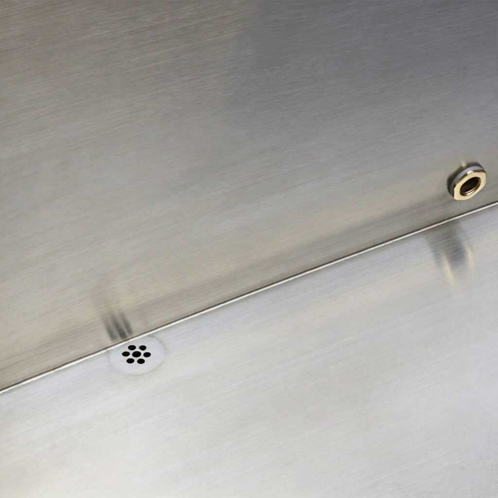
Separate four water events: routine splash, condensation, filter or hose service, and an abnormal leak or drain-down. For each one, define where water goes, how it is contained and which materials it can contact. A floor drain is useful only when its location, capacity, trap, backflow arrangement, threshold and discharge permission match the project. “There is a drain somewhere in the room” is not a plan.
Use the five-event floor-drainage approval record to expand this room check into condensation, splash/overflow, planned drain-down, service water and abnormal-leak routes with a permitted destination and staged test.
Keep this check at interface level. The room drawing should show the destination and access route, while the local designer decides gradients, waterproofing, penetrations and code details. The future specialist decision for floor-drain design is intentionally not replaced here. For the current indoor cold plunge installation, the release question is whether a lawful, maintainable and visible water path exists before equipment placement.
4. Calculate where chiller heat will go
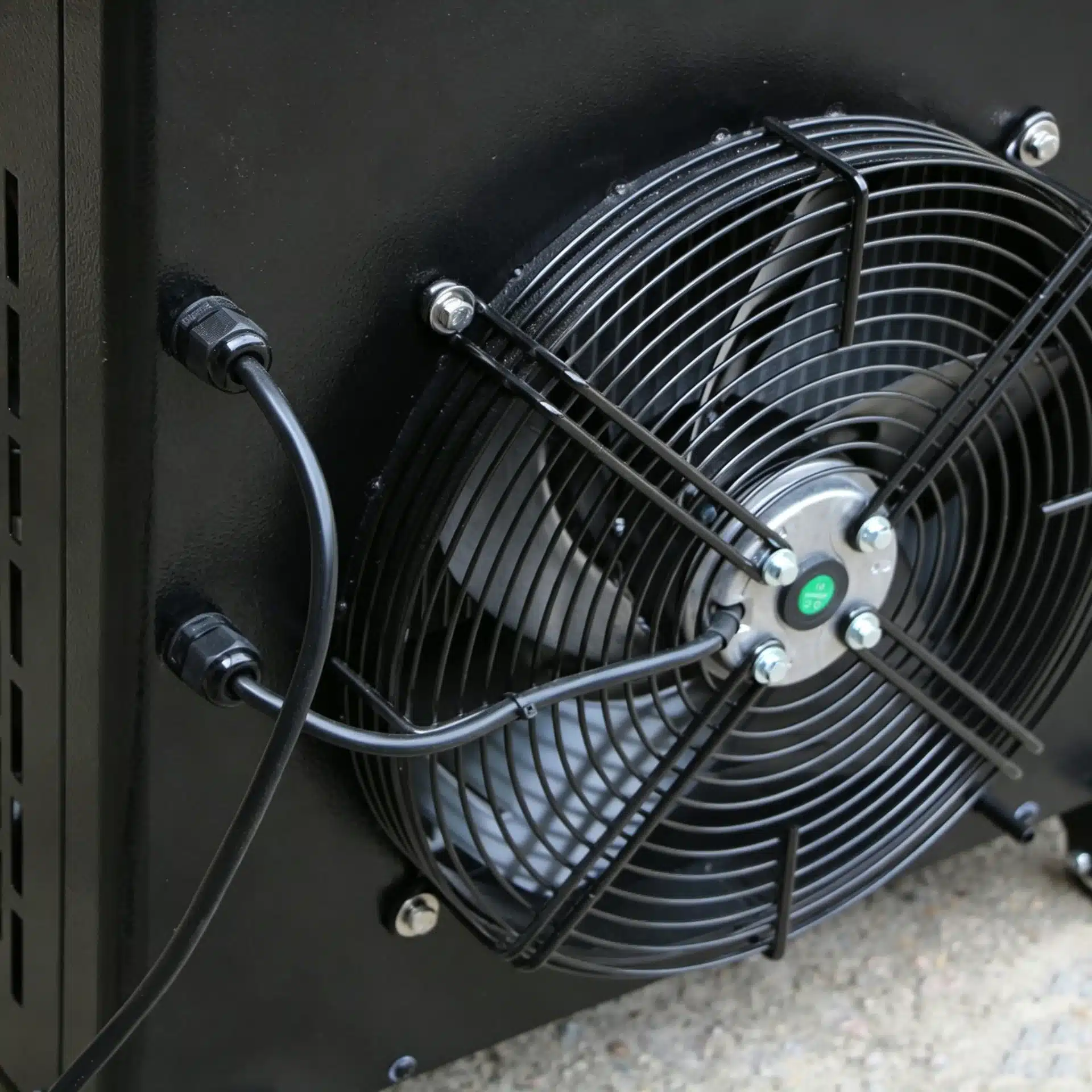
An air-cooled chiller moves heat out of the water and releases that heat, plus its electrical input, into the surrounding air. A compact room or decorative cabinet can recirculate the warm exhaust back into the intake. The consequences may include a hotter room, longer run time, reduced cooling capacity, nuisance protection events and uncomfortable users. An open grille in a joinery panel is not automatically adequate ventilation.
Obtain the exact model’s intake direction, discharge direction, minimum clearances and operating ambient range. Ask the room designer to state how the heat is removed at the expected duty, not just at an empty overnight pull-down. The chiller sizing-by-volume checklist identifies the water-side load, and the horsepower guide explains why HP alone does not state usable capacity. The indoor room still needs its own heat-rejection answer.
For the equipment-side data request, use the heat-rejection and room-load worksheet to separate package discharge from the complete room balance before accepting a cabinet or ventilation proposal.
5. Control humidity and condensation at the room boundary
A cold tub, hoses, valves and filter housings can sit below the room’s dew point, so moisture may appear even when no fitting leaks. Bathers, cleaning and an uncovered water surface add more moisture. The indoor cold plunge installation plan should identify cold surfaces, insulation continuity, drip collection, room ventilation or dehumidification, monitoring and finishes that can tolerate the expected conditions.
The U.S. EPA’s mold and moisture guide advises controlling indoor humidity and acting quickly when condensation or moisture collects. Its numerical guidance is not a universal design setpoint for every country or commercial room, but the principle is directly useful: moisture needs a source-control and drying strategy. The cold plunge insulation guide covers the detailed thermal-boundary decision; this room check confirms that the selected insulation and building moisture plan meet at the installation.
6. Approve the wet-location electrical route
Record the actual nameplate voltage, frequency, rated current or input, plug or termination, required protective devices, grounding or bonding instructions, isolator location and cable route. Then have a qualified local electrician assess the installation around water. Plug shape is not approval. An extension lead, travel adapter or socket hidden behind a wet tub should be treated as an unresolved design condition, not a temporary convenience.
For U.S. readers, the CPSC’s pool and spa electrical-safety guidance emphasizes GFCI protection, cord separation from water and inspection by a qualified electrician familiar with applicable rules. OSHA’s general electrical requirements also state that listed or labeled equipment should be used according to its instructions and that working space must permit safe operation and maintenance. These are U.S. sources with defined scopes; the project must follow the destination’s current rules and the exact equipment instructions.
Use the 110V versus 220V importer guide to capture the electrical fields before an RFQ. A clean indoor cold plunge installation record distinguishes supplier data from the electrician’s site approval and does not let either party silently assume the other accepted the final route.
7. Preserve water-loop geometry and hose protection
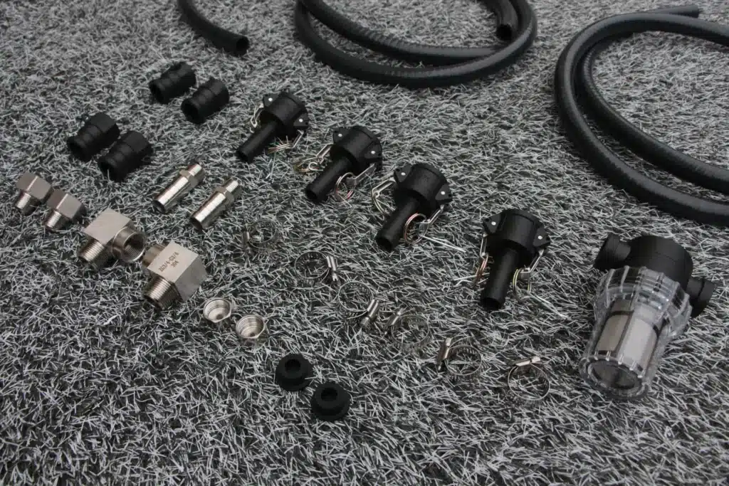
Draw the route from tub outlet to pump, filter, chiller and return. Show elevation changes, hose lengths, internal diameters, fittings, valves, strainers, isolation points and the position used to drain or purge the loop. A long hidden run added by the room designer can change pressure loss and priming even when the equipment schedule stays the same.
Protect hoses from feet, doors, cleaning carts, sharp bends, crushing and accidental disconnection. Avoid trapping a flexible line where it cannot be inspected for sweating or leakage. If a wall or cabinet penetration is required, define its sleeve, edge protection, seal and access before finishes close. The pump-not-drawing-water diagnostic shows why air entry, restriction and route geometry should be prevented during design rather than investigated after handover.
8. Make the water supply, fill and discharge method explicit
State how the tub is filled, topped up, sampled, cleaned and emptied. Identify the water source, hose-control or backflow provisions assigned by the site designer, maximum acceptable fill time and the destination for treated or cleaning water. Never assume that water containing a disinfectant or cleaning chemical may be discharged to any convenient drain.
The indoor cold plunge installation supplier can identify drain connections and water-side material limits, but the building owner and local professionals control the site water route. A shared-use indoor cold plunge installation also needs an operating water-care plan. The commercial filter-system checklist separates circulation, filtration, treatment and recordkeeping so the room plan does not mistake a cartridge filter for a complete hygiene decision.
9. Choose wet-area finishes and a safe user route
Map the person, not just the equipment. Show approach, changing, entry, exit, hand support, towels, wet feet, supervision and the route used when the room is being cleaned or the tub is unavailable. Select floor, wall, skirting, sealant, nearby furniture and metal finishes for the expected wetting and cleaning regime. A photograph of an attractive dry showroom says nothing about performance after repeated wet sessions.
Accessibility is a project input for covered facilities. The U.S. Access Board’s ADA standards resource includes requirements for accessible routes and certain pool and spa facilities. A cold plunge should not be assigned a legal classification from this article; the owner and qualified designer must determine which local provisions apply. The practical early question is whether the planned entry method and surrounding clear space exclude users or conflict with required circulation.
10. Check noise, vibration and neighbouring spaces
Compressors, pumps, fans and water movement create different sound and vibration patterns. Record the proposed equipment position relative to treatment rooms, hotel bedrooms, offices, residences and the user’s head position. Ask for model-specific sound data when available, but do not treat one laboratory value as the installed result. Walls, corners, platforms, flexible connections and operating speed can change the experience.
For a comparable data request, use the cold plunge chiller noise test conditions to record operating state, instrument, microphone position, background, room and vibration path before accepting a decibel claim.
Provide a stable, level support and any manufacturer-permitted vibration treatment. Do not improvise thick pads that obstruct wheels, ventilation, drainage or service panels. For hospitality projects, the hotel cold plunge planning guide connects noise and downtime to guest operations; this indoor cold plunge installation check stays focused on the physical room interface.
11. Prove delivery, assembly and replacement access
Measure the packed and unpacked equipment, weight of the heaviest item, turning radius, lift capacity, door clear openings, thresholds, stairs, ceiling restrictions and final assembly area. Confirm whether handles, panels, steps or pipe stubs can be removed for entry without invalidating the product or damaging finishes. An indoor cold plunge installation can have enough operating area and still be impossible to reach with the delivered tub.
Repeat the exercise for replacement. Chillers and pumps are serviceable equipment; the route should not depend on demolishing cabinetry or lifting a filled tub. Photograph critical access points, attach dimensions to the approved drawing and resolve protection for floors and door frames before shipment. This is especially important for an overseas order, where discovering a narrow turn after arrival creates storage, labour and delay costs.
The cold plunge chiller service-access schedule expands that route into operating, routine-service and full-replacement envelopes for panels, filters, pumps, drains and the complete unit.
12. Assign every interface and acceptance signature
The final indoor cold plunge installation check is ownership. Name who approves structure, waterproofing, drainage, ventilation or dehumidification, electrical work, water supply, equipment selection, loop integration, finishes, accessibility, installation, water care and commissioning. “By others” is not a person. Each open item needs a responsible party, required evidence, due date and the authority that can accept or reject it.
Freeze the accepted room-interface schedule with a revision. If the model, room, hose length, cabinet, drainage destination or electrical route changes, send the affected checks back for review. The cold plunge commissioning checklist covers the installed operating baseline; room approval must happen earlier so commissioning is verification, not emergency design.
Use one room-interface schedule before releasing the order
The table below is the working spine of an indoor cold plunge installation. It turns broad questions into deliverables. Add project values, drawing references and signatures; do not replace evidence with a green status cell.
| Interface | Supplier must provide | Site team must provide | Release evidence |
|---|---|---|---|
| Identity and duty | Exact models, drawings, usable volume, temperatures, flow, ambient and clearance limits | User pattern, room conditions and approved operating duty | Signed equipment schedule and duty sheet |
| Load | Dry mass, filled volume, footprint and support points | Accepted structural location and support detail | Qualified written confirmation or drawing |
| Water events | Ports, normal drain method, service drain volume and material limits | Containment, floor construction and lawful discharge route | Drainage/waterproofing drawing with owner |
| Heat | Heat-rejection basis, airflow direction, clearances and ambient range | Room ventilation or heat-removal design | Coordinated mechanical layout |
| Moisture | Cold surfaces, insulation and permitted operating range | Humidity strategy, finish selection and monitoring | Moisture-control note and inspection points |
| Electrical | Nameplate, wiring/plug, protection and installation instructions | Qualified local design, circuit, isolation and route | Electrical drawing and approval |
| Water loop | Permitted flow, ports, component sequence and service method | Final route, protection, penetrations and measured design assumptions | Coordinated loop diagram |
| Access | Packed dimensions, heaviest piece, panels and removal clearances | Surveyed delivery, operating and replacement route | Access survey with minimum dimensions |
| Handover | Manuals, checks, training scope and supplier contacts | Operators, local inspections and shutdown authority | Commissioning and responsibility plan |
Run a combined heat-and-moisture thought test
Project teams often review heat, humidity and drainage in separate meetings. The room experiences them together. Imagine the indoor cold plunge installation during the busiest hour: the cover is open, wet users enter and leave, the pump and chiller run, the condenser warms the air, cold hoses sweat, the filter is opened for service and a door closes for privacy. Now ask where heat, vapour and liquid water go.
Use three documented conditions: normal covered holding, peak occupied operation and planned service or drain-down. For each, record room temperature and humidity design assumptions, chiller state, open-water time, expected wet surfaces, ventilation state, drain path and who observes abnormal moisture. This is not a substitute for engineering calculation. It is a coordination test that exposes contradictions, such as an exhaust fan disabled during occupied hours or a drip tray that cannot be emptied without crossing an electrical route.
If condensation remains unexplained, return to the insulation and room-HVAC decisions. If the room cannot remove rejected heat, reconsider location, enclosure or equipment arrangement before increasing chiller size. A larger unit can introduce more heat and airflow demand; it does not repair a blocked plant space.
Keep the electrical decision independent and visible
The supplier should never approve a destination’s building wiring, and the local electrician should not have to infer product requirements from a sales page. Put the nameplate, manual, equipment layout and water boundaries in one review package. Mark disconnects and emergency controls so staff can identify them without reaching across water or moving the machine.
For an indoor cold plunge installation in a commercial facility, preserve safe access to electrical equipment after furniture, towels, storage and acoustic treatment are added. Test protection and isolation under the applicable local procedure before first use, then include the required inspection or test interval in the maintenance plan. The chiller maintenance checklist can carry recurring equipment tasks after the site’s qualified electrical requirements are defined.
Draw three layouts: use, service and removal
A single architectural plan usually shows the room during normal use. Add two overlays. The service overlay should show filter opening, valve operation, panel removal, cleaning, sampling, draining and the position of a technician with tools. The removal overlay should show how the chiller, pump or tub leaves the room. Any clash found on paper is cheaper than the same clash behind a finished wall.
In a wellness business, customer flow and operating economics are separate decisions. Use the wellness-studio planning guide for booking, staff and service design. For this indoor cold plunge installation, the pass condition is physical: users and staff can reach what they need without blocking airflow, pulling hoses, stepping over cables or losing the clearances stated by the equipment manufacturer.
Indoor cold plunge installation plans that look finished but fail
- The hidden-chiller cabinet: joinery conceals the unit but recirculates hot discharge and blocks panel removal.
- The distant drain: a floor drain exists, yet the hose must cross a walkway and the service tray cannot reach it.
- The dry-showroom floor: finishes look premium before use but have no documented wet-area, cleaning or slip strategy.
- The socket solution: voltage matches, but the circuit, protective device, isolation, bonding/grounding and wet-location route were never reviewed.
- The volume-only load: water mass is calculated, but support points, users, steps and local floor construction are omitted.
- The long hose surprise: the final room layout adds bends and distance after the pump and filter were selected.
- The sealed room: privacy and acoustic measures close the space while the chiller and wet users add heat and moisture.
- The permanent installation: equipment fits after assembly, but a failed chiller cannot be removed without moving the tub or cutting cabinetry.
- The shared responsibility gap: supplier, plumber, electrician and designer each approve their component, while nobody signs for the connected interfaces.
None of these failures is solved by adding the words “professional installation” to a quotation. The evidence belongs in drawings, model data and named approvals. If the project is outside, use the separate outdoor cold plunge site checklist for weather, sun, freezing, wind and exterior exposure; those are not the duties of this indoor room guide.
Accept the room before accepting the operating system
Before equipment energization, inspect the room against the approved revision. Confirm location, level support, clearances, water containment, drainage destination, electrical completion, hose protection, ventilation path, service access and delivery/removal route. Photograph the interfaces and record deviations. Do not cover a disagreement with “as installed” until the responsible reviewer accepts the change.
Then commission the connected system under representative conditions: leak and prime checks, verified flow basis, temperature pull-down, holding behaviour, control and alarm observations, heat rejection, condensation, drain-down, electrical sign-off and staff handover. The factory acceptance checklist verifies the identified equipment before shipping; site commissioning proves that equipment and room now work together.
Copy this indoor cold plunge installation block into the RFQ
INDOOR COLD PLUNGE ROOM INTERFACE SCHEDULE

Buyer / project / destination: [ ]
Site type and intended use: [home / gym / hotel / spa / clinic / other]
Responsible system integrator: [ ]

Tub model / revision / dry mass: [ ]
Usable water volume / approved fill line: [ ]
Maximum users at one time: [ ]
Chiller model / electrical variant: [ ]
Pump / filter / water-care components: [ ]
Hose or pipe sizes and total route: [attach drawing]

Approved support surface and load reviewer: [ ]
Tub / chiller / step footprints and support points: [attach]
Delivery route minimum door, turn, lift and threshold dimensions: [ ]
Replacement-removal route: [ ]

Routine splash and condensation containment: [ ]
Filter-service and full drain-down route: [ ]
Abnormal leak containment: [ ]
Approved discharge destination / local owner: [ ]

Room design temperature and humidity range: [ ]
Chiller heat-rejection data and airflow direction: [attach]
Required intake / discharge / service clearances: [ ]
Ventilation or heat-removal design owner: [ ]
Condensation / insulation / dehumidification plan: [ ]

Verified voltage / frequency / nameplate input: [ ]
Dedicated circuit / protective devices / isolation: [ ]
Grounding or bonding and wet-location review owner: [ ]
Cable route separated from wet and service paths: [attach]

User entry / exit / hand support / clear route: [attach]
Wet-area floor, wall and cleaning finish specification: [ ]
Accessibility review and applicable local requirements: [ ]
Noise and vibration acceptance basis: [ ]

Room approval revision and date: [ ]
Open deviations / owner / due date: [ ]
Factory test requirements: [attach]
Site commissioning and handover requirements: [attach]
Authority to approve, conditionally approve or hold: [ ]
Attach this field block to the OEM chiller RFQ template. The first document tells the supplier what the room can support; the second asks the supplier to identify a configuration and its assumptions. Together they prevent a quotation from quietly moving unresolved site work back to the buyer.
Buyer next step: send the room, not just the desired temperature
A useful indoor cold plunge installation enquiry includes the room drawing, door/access survey, water volume, target and starting temperatures, ambient and humidity range, user schedule, verified electrical supply, drain destination, hose route, ventilation concept and service clearances. It also identifies what is fixed and what may still change. That gives the supplier enough context to reject a poor location, state assumptions or propose a more suitable arrangement.
Review OMNI’s cold plunge chiller configurations, then send the completed interface schedule through the project contact form. OMNI can discuss available equipment and documentation against the stated duty; the project’s qualified site team remains responsible for structure, drainage, electrical work, building moisture, accessibility and local approval.
Indoor cold plunge installation FAQ
Can an indoor cold plunge go in any room with a floor drain?
No. The room also needs verified load support, water containment, a permitted discharge route, heat rejection, humidity and condensation control, qualified electrical installation, protected circulation routing, safe user access, service space and an equipment delivery/removal path. A drain answers only one part of the decision.
Does an indoor cold plunge room need ventilation?
The room needs a documented strategy for chiller heat and moisture. The answer may involve ventilation, air conditioning, dehumidification, equipment relocation or a combination, depending on the exact unit, room and operating pattern. Use model-specific heat-rejection and airflow data plus a qualified room assessment.
How much service clearance should I leave around the chiller?
Use the exact manufacturer’s installation and service dimensions. Airflow clearance and technician working space are different requirements. The layout should allow filters, valves and panels to be reached and should also provide a route to remove the chiller without moving a filled tub.
Can I use an extension cord for a cold plunge chiller indoors?
Do not assume an extension cord or adapter is acceptable near water. Follow the exact equipment instructions and have a qualified local electrician design and inspect the circuit, protective devices, isolation, grounding or bonding and cable route for the destination and wet environment.
What should be approved before ordering an indoor cold plunge system?
Approve the exact system identity, filled load, support, water containment and discharge, heat and humidity strategy, electrical route, water-loop geometry, wet-area finishes, user and service access, delivery/removal route, local review responsibilities and the acceptance plan. Hold the order when a safety-critical or equipment-selection interface is still unknown.