Cold plunge chiller service access must be drawn before the equipment is ordered, not measured after a filter, panel or pump needs attention. The layout should show three different envelopes: normal operation, routine service and major component or full-unit removal. A clearance that admits air is not automatically large enough for a technician, tool, drain container or replacement part.
This article helps facility designers, installers, distributors and commercial operators freeze nine access spaces around a chiller. It covers filters, panels, fan/coil surfaces, water connections, drainage, electrical isolation, refrigeration-service boundaries, component movement and full-unit replacement. It does not provide live electrical, refrigerant or internal repair instructions.
Cold plunge chiller service access uses three envelopes
Do not draw one generic rectangle labelled clearance. Separate the space required while the chiller runs from the space needed for recurring care and the route needed for major service or replacement.
| Envelope | What it protects | Examples to draw | Acceptance question |
|---|---|---|---|
| Operating envelope | Airflow, normal water connections, drainage and controls while panels are closed | Intake/discharge faces, hose bends, cable route, drain and controller view | Can the exact unit operate in the finished room without an open door or moved furniture? |
| Routine-service envelope | Tasks expected during operation and preventive maintenance | Filter bowl or cartridge removal, strainer cleaning, panel opening, coil cleaning and leak inspection | Can the task be completed with approved isolation and without dismantling unrelated finishes? |
| Major-service/replacement envelope | Qualified access to internal components and removal of the complete unit | Tool/working position, component travel, lifting/handling aid and route to a door or loading point | Can a failed unit or major component leave the site without moving a filled tub or destroying joinery? |
These envelopes can overlap but they answer different questions. A narrow grille may keep a cabinet visually open while providing no path to remove the filter. A removable front panel may expose components while a wall prevents the panel from clearing its fasteners. A wide service aisle may still fail if the chiller cannot turn through the room door.
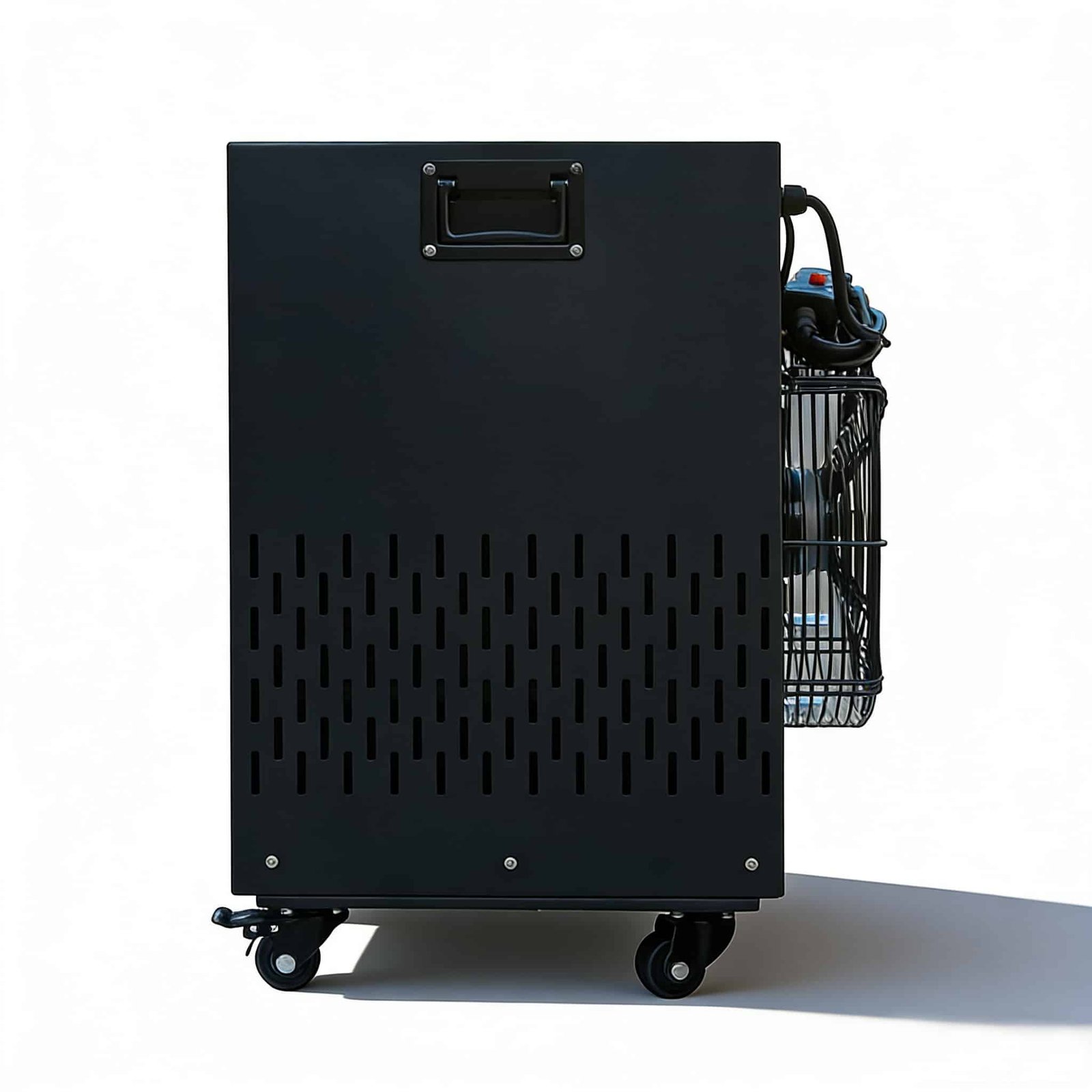
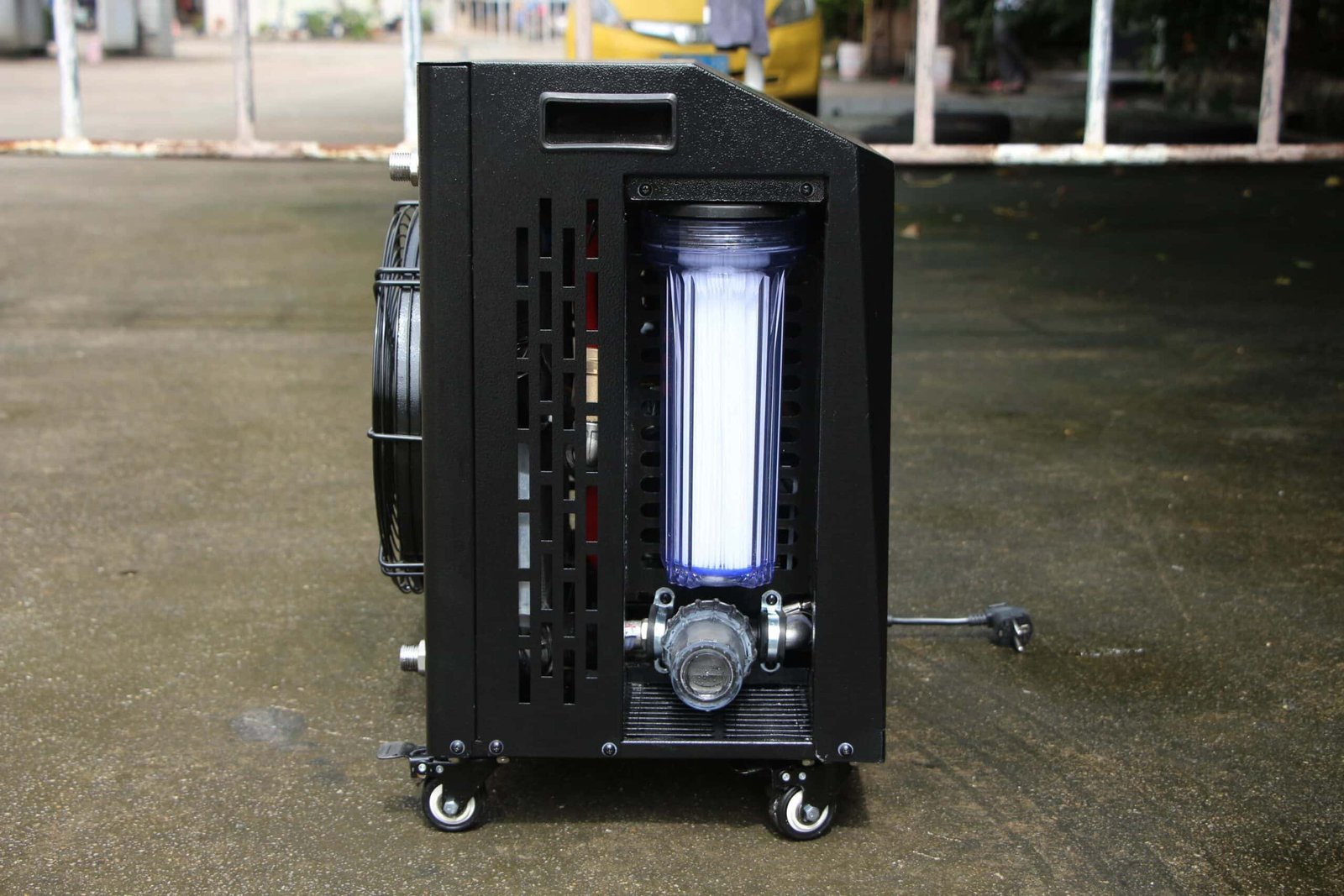
Use the exact model drawing and actual component arrangement. Different product families use internal or external pump/filter arrangements. Do not assume one photograph or C-type drawing represents every CHM, CHU or other series. The chiller configuration page helps identify the product route; the access schedule should name the offered model and revision.
Nine spaces to draw for cold plunge chiller service access
Use this table as an access-request checklist. Replace each broad item with dimensions and component identity from the exact offered unit. Do not copy one universal distance across every face.
| Space | What to mark | Why the buyer needs it |
|---|---|---|
| 1. Intake-air space | Air source, nearby wall/screen, debris risk and normal panel position | Prevents restricted entering air and hidden cleaning points |
| 2. Discharge-air space | Discharge direction, recirculation barrier and heat destination | Keeps warm air from returning to the intake or occupied space |
| 3. Panel movement | Hinge/swing or lift-off direction, fastener access and storage position | A panel cannot be removed through a finished wall or tub |
| 4. Filter removal | Bowl, lid or cartridge travel, grip position, drain/spill zone and replacement length | Routine care fails when the filter can open only part-way |
| 5. Pump/strainer access | Isolation, unions, visible leak points, cleaning position and component travel | Supports inspection and replacement without disturbing the whole loop |
| 6. Water-port and hose space | Connector movement, bend radius, valves, caps and tool access | Prevents kinked hoses, inaccessible unions and water running toward electrical parts |
| 7. Drain and spill-control space | Service-drain container, hose route, floor protection and lawful destination | Separates planned maintenance water from an uncontrolled leak |
| 8. Qualified electrical/refrigeration work zone | Isolation point, guarded boundary and approved technician position | Prevents routine operators from improvising hazardous internal work |
| 9. Component and full-unit removal route | Heaviest/removable pieces, handling aid, turns, thresholds, doors and loading point | Allows repair or replacement without dismantling the facility around the machine |
Cold plunge chiller service access should be shown in plan and elevation. A plan view captures walls, tub position and working aisle. An elevation captures filter drop, panel lift, cable/pipe entries and overhead restrictions. Add a route view for full-unit removal. A single product footprint cannot answer all three.
Filters, strainers and pumps need wet service space
Water-side maintenance creates both a movement problem and a water-control problem. Draw where a filter bowl, cartridge or strainer lid travels when opened. Mark the container or drain path for retained water. Show which valve or isolation method limits drain-down and where a technician can grip the component without reaching across electrical equipment.
The cold plunge floor-drainage schedule connects this retained service water to the wider room route, receiving destination, protected dry areas and acceptance test.
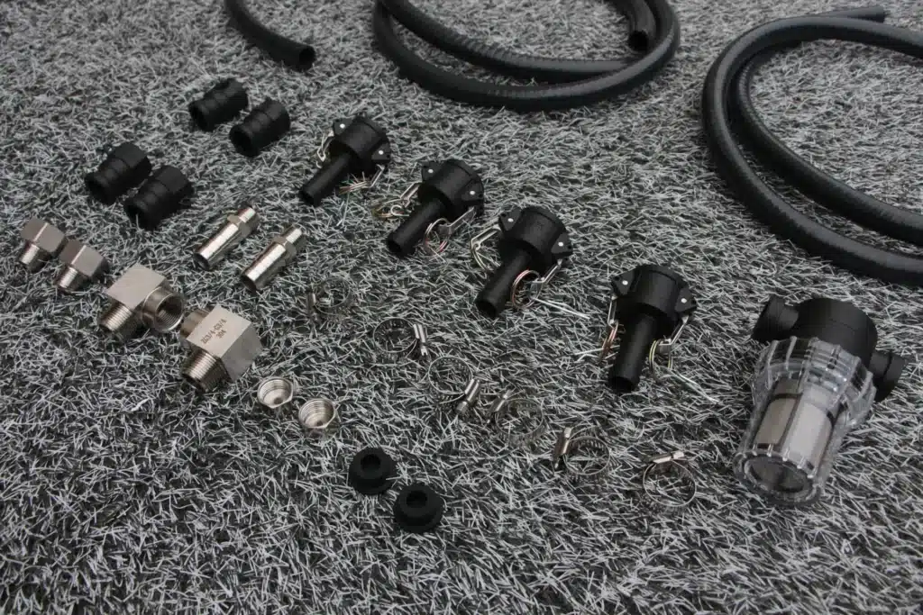
Component identity matters. One product may have a visible external filter housing and pump on a side face. Another may integrate circulation and filtration inside the cabinet. A separate system may place a hair strainer and secondary filter between the tub and chiller. Cold plunge chiller service access must follow the exact architecture rather than a generic sequence copied from another model.
Use the cold plunge chiller filter guide for filter-condition and flow questions, and the facility filter-system guide when the project has multiple external components. Those pages define what the water loop must do. This page defines whether people can inspect and service the selected arrangement.
Keep hose bends and unions visible. A connection hidden behind a fixed panel cannot be checked for sweating, seepage or accidental loosening. A hose forced into a sharp bend to save floor space may create restriction and shorten the working life of the connection. The pump troubleshooting guide explains first checks after a symptom; the drawing should prevent avoidable access and routing problems before handover.
Do not solve airflow by blocking the service panel
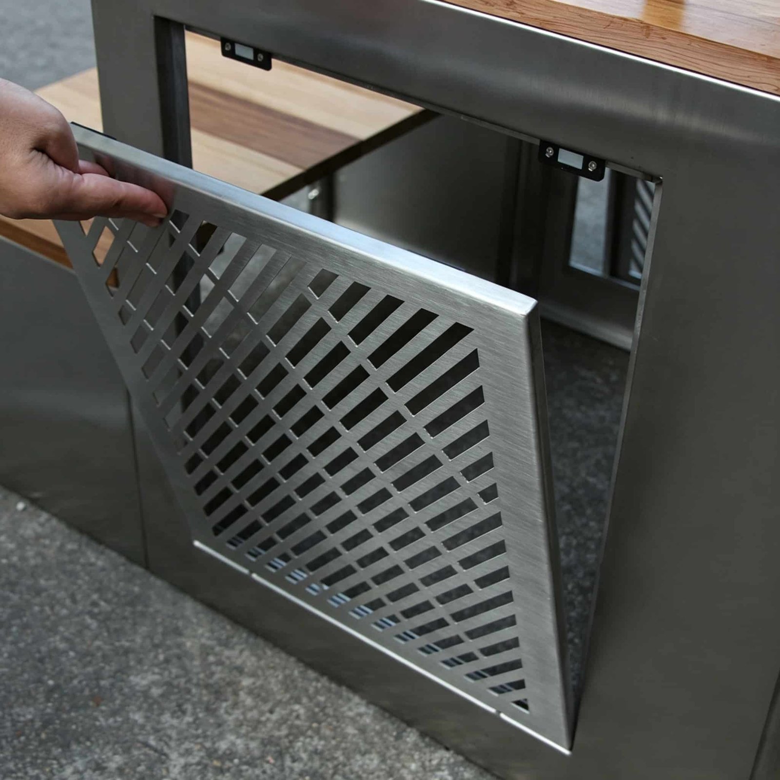
Air-cooled equipment needs an identified intake and discharge path with normal panels in place. The same face may also carry a removable guard, coil-cleaning surface, fan, filter module, cable or water ports. Draw the air path and maintenance action together. A decorative grille can preserve airflow while still preventing a hand, brush, fastener tool or replacement part from reaching the equipment.
Available installation documents can use different orientation conventions and clearance dimensions across a manual and a heat-placement drawing. Until the exact model, version and discharge direction are reconciled, do not publish one universal front/rear value or choose the smaller number. Require the supplier to mark each face on the product drawing and state the applicable operating, cleaning and service envelope.
Cold plunge chiller service access also needs the normal cabinet state. If a unit runs only when a joinery door is open, the operating design is incomplete. If a service panel can be removed only after the tub is drained and moved, record that dependency and decide whether it is acceptable. The heat-rejection guide separates the air-side equipment boundary from the room decision.
Keep hazardous maintenance behind the qualified-service boundary
The United Kingdom Health and Safety Executive advises that machinery maintenance should be planned, performed by competent people and carried out with equipment made safe through isolation where required. The HSE maintenance of work equipment guidance addresses workplace machinery generally, not cold-plunge products. It supports a clear division between routine external care and qualified internal service.
Routine operators may need safe access to external filters, visible hoses, drain points, controller information and approved cleaning surfaces. Internal electrical diagnosis, live measurements, protection-setting changes, refrigeration opening and refrigerant work belong to the exact manual and qualified service route. Do not turn an internal fault table into a general user procedure.
Mark the isolation and shutdown responsibility in the access schedule without publishing a universal wiring method. Different model families and controller versions can assign the same error code to different faults. Cold plunge chiller service access should help a technician identify the exact unit and reach the approved service point; it should not imply that one error code or internal operation applies to every controller.
Store service records outside the wet work zone. The technician needs the model, serial, electrical version, manual revision, symptom, prior changes and approved parts before opening a qualified work order. The cold plunge chiller maintenance guide can carry recurring external tasks; service access determines whether those tasks remain practical after the room is furnished.
Prove the component and full-unit removal route
Draw the largest component that may need to leave each access face, then draw the complete chiller route to the door, lift or loading point. Include handles, casters, pallet/trolley use, turning envelope, thresholds and the position of the tub when full. Do not assume the replacement route is the same as the original construction route; walls, doors and finishes may have been completed after delivery.
For a cabinet installation, identify which panels are removable and in what order. If the unit must slide out, show how hoses, cable and drains are isolated and protected before movement. If an overhead lift or two-person handling method is required, confirm the site can use it. Do not invent weights or lift points from the cabinet appearance.
The portable chiller move-cycle guide covers draining, disconnection, transport, reconnection and recommissioning. A wheeled unit can still fail cold plunge chiller service access if the handle cannot extend, the route is too narrow or the connected system cannot be returned to an accepted state.
| Finding | Decision |
|---|---|
| All routine components can be reached, drained and removed under the approved isolation method | Accept the routine-service envelope and retain the drawing |
| Airflow is available but a filter, panel or union cannot complete its movement | Revise the room, cabinet or component orientation before release |
| Major service requires moving a filled tub or demolishing fixed finishes | Hold the layout or formally accept and price that lifecycle constraint |
| The service route depends on unverified component weights, access faces or internal architecture | Request the exact model drawing and service information |
Run the service sequence on the drawing
Choose three representative tasks before approving the layout: a routine filter service, investigation of a water-side leak and removal of the complete chiller. Walk each task from shutdown through access, water control, component movement, reassembly and recommissioning. The aim is not to create a repair manual. It is to expose missing space and responsibility.
For each task, ask: Which panel or fitting moves first? Where does retained water go? What must remain dry? Which tool or handling aid needs space? Can the technician see the model and connection labels? Does the task block user circulation or another machine? Which qualified boundary stops routine staff? What evidence returns the system to service?
Illustrative layout review, not an OMNI project case: a cabinet drawing shows enough open area beside a chiller, but the filter bowl projects downward and the finished plinth leaves no room for removal. The plan view appears acceptable; the elevation reveals the failure. Raising the cabinet without checking hose and user access may create another problem. The correct revision coordinates the filter travel, spill container, hose bends and unit-removal path on the same set.
Cold plunge chiller service access is accepted when another reviewer can reproduce the route from the drawing and component list. A note saying “maintenance space provided” is not measurable and should not close the decision.
Photograph the approved access faces after installation with the normal tub, cabinet, storage and floor finishes in place. Add one image showing the panel or filter at its fully open removal position, not only a closed beauty shot. Tie each photograph to the drawing revision and equipment identity. This gives maintenance teams a usable baseline and makes later furniture, joinery or hose-route changes visible.
If the accepted cold plunge chiller service access is reduced later, treat the change as an installation decision. Recheck airflow, water control, routine tasks and the replacement route before relying on the old approval. A technically serviceable machine can become inaccessible after a shelf, acoustic lining or storage rack is added.
Copyable cold plunge chiller service access schedule
- Equipment: exact model, revision, serial/sample, electrical variant and component architecture.
- Operating faces: intake, discharge, controls, water ports, drain and normal panel positions.
- Routine tasks: filter/strainer, pump, coil/guard, hose/union, leak observation and cleaning points.
- Panel movement: fastening, hinge/lift direction, movement envelope and safe storage position.
- Water control: isolation, retained volume, drain container/route, spill protection and wet/dry separation.
- Qualified boundary: shutdown/isolation responsibility, electrical and refrigeration access, required competence and service contact.
- Component removal: movement direction, dimensions/weight from supplier, handling aids and obstruction check.
- Full-unit route: floor path, turns, doors, thresholds, lift/loading point and tub state.
- Return to service: reconnection, prime, leak, flow, controller, alarm and approved operating verification.
Add this schedule to the OEM cold plunge chiller RFQ template and the indoor installation room package. To review a specific OMNI configuration, send the equipment model, room plan and service/removal route. Do not leave cold plunge chiller service access as unused space around a generic rectangle.
At quotation stage, ask the supplier for a component-and-access sheet rather than a cabinet footprint alone. It should name the access face for each routine component, the movement direction, any retained water, the required isolation boundary, and the largest part that may leave the cabinet. If the supplier cannot provide dimensions yet, mark the layout provisional and keep joinery or fixed walls outside the expected service zone.
At handover, demonstrate only the approved external maintenance actions: view the labels, reach the controller, open the permitted panel, position the service-drain container, remove the accessible filter element and trace the full-unit exit route. Record every task that requires a qualified technician rather than performing it as part of the demonstration. This cold plunge chiller service access check converts the drawing into an operating baseline without turning the handover into an internal repair lesson.
Questions buyers ask about service access
Is airflow clearance the same as cold plunge chiller service access?
No. Airflow clearance supports operation. Service access must also allow safe isolation, panel movement, component inspection/removal, water control, technician position and full-unit replacement.
How much service space should I leave?
Use the exact orientation-specific installation and service drawing for the offered model. Do not copy one universal distance. Add the movement envelope for each filter, panel and component plus the complete replacement route.
Should the filter be accessible without moving the chiller?
For routine maintenance, the preferred layout allows the approved filter service without moving unrelated equipment or a filled tub. If movement is required, document the shutdown, drain, handling and recommissioning consequence before approval.
Can facility staff open the chiller cabinet?
Only within the tasks and boundaries stated by the exact manual and site procedure. Internal electrical and refrigeration work should remain with qualified service personnel.
What should a cold plunge chiller service access drawing include?
Show operating airflow, panels, filters, pump/strainer, water ports, drain/spill control, qualified work zone, component movement and the full-unit removal route with responsibilities and return-to-service evidence.