Cold plunge chiller floor drainage should be approved as five separate water events: condensation and routine drips, user splash or overflow, planned tub drain-down, filter and maintenance water, and an abnormal leak. A floor drain near the equipment is not a complete plan unless each event has a capture path, permitted destination, response responsibility and acceptance test.
This article is for facility designers, installers, distributors and commercial operators defining a cold-plunge room before purchase or handover. It provides a five-event drainage map, a simple discharge-rate calculation, an eight-field approval schedule and a commissioning test. It does not prescribe one floor slope, drain size, waterproofing system or discharge destination for every project; the building design, equipment instructions and applicable local requirements remain controlling.
Cold plunge chiller floor drainage starts with five water events
The first design step is not choosing a drain. It is naming the water sources and the condition under which each appears. These events differ in volume, duration, cleanliness, predictability and response time, so one generic arrow marked “to drain” can hide several unresolved decisions.
| Water event | Typical source | Design question | Acceptance evidence |
|---|---|---|---|
| 1. Condensation and routine drips | Cold tub wall, hoses, fittings, filter housing or wet users | Where does low-rate water collect, dry or drain without reaching finishes or electrics? | Observed dry/wet condition under representative humidity and operation |
| 2. Splash and overflow | User entry/exit, displaced water, fill error or wave action | Can the floor contain the event without sending water into circulation routes, doors or equipment? | Marked wet zone, threshold/containment review and housekeeping route |
| 3. Planned drain-down | Tub emptying, seasonal shutdown or water replacement | Can the selected outlet, hose and receiving drain handle the planned flow and total volume? | Timed drain trial or documented capacity route with permitted destination |
| 4. Service water | Filter bowl, strainer, pump, hose disconnection or cleaning | Where is retained water captured while a component is opened or removed? | Task walk-through with container/drain position and dry electrical boundary |
| 5. Abnormal leak | Loose fitting, split hose, seal failure, overflow control failure or damaged vessel | What contains the first release, detects it and stops additional water? | Leak-response map, isolation responsibility and safe access to shutdown |
A cold plunge chiller floor drainage plan passes only when the five events are distinguished. A route suitable for slow condensation may be overwhelmed by planned drain-down. A drain hose that works during maintenance may cross a user path. An emergency leak may begin when no operator is standing beside the tub.
The cold plunge chiller floor drainage decision therefore connects each water source to a different design and response boundary instead of asking one drain symbol to represent every event.
The indoor cold plunge installation guide owns the full room decision across structure, heat, humidity, electrical work, access and drainage. This page goes deeper on the liquid-water route and its acceptance record.
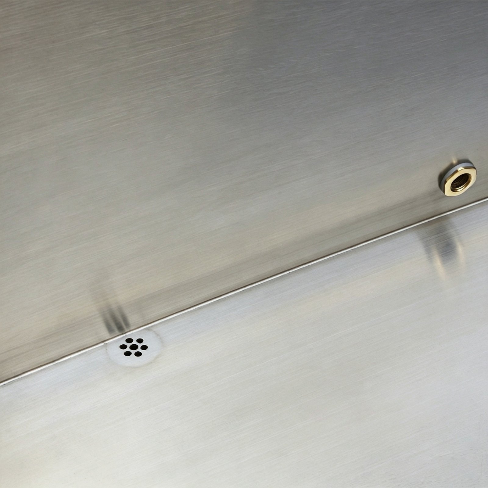
Draw the water route from source to approved destination
Use a plan view and an elevation. The plan view should show the tub, chiller, pump/filter, service faces, wet zone, floor drain or collection point, thresholds, doors, walking routes, walls and electrical equipment. The elevation should show outlet heights, hose fall, raised bases, traps or air gaps specified by the project, and any point where water can remain trapped.
Mark the route for each of the five events. A cold plunge chiller floor drainage drawing should answer:
- where water first leaves the tub, component or surface;
- whether it moves by gravity, a removable hose, a fixed pipe, a pump or manual collection;
- which floor area can become wet and which must remain dry;
- which thresholds, door tracks, plinths, mats, cable routes or equipment feet can interrupt the path;
- where the water is legally and practically received;
- who sets up, observes, cleans and returns the route to normal.
Do not assume a floor that looks level drains toward the intended point. Verify the constructed surface and the effect of the actual equipment. A chiller base, levelling foot, anti-vibration pad, cabinet plinth or storage item can create a local dam. A removable hose can develop a high point or kink that leaves water inside the tub or directs the final release across the floor.
Review cold plunge chiller floor drainage with the normal equipment, doors, mats, steps and service panels in place; an empty room can hide the barriers that control the real water path.
Keep drainage separate from the equipment airflow and service plan. A trench, curb or floor recess should not block casters, panel movement, filter removal or the full-unit exit route. The cold plunge chiller service-access schedule helps coordinate component movement with retained-water control.
Calculate planned drain-down before choosing the route
For planned emptying, record the volume that will be released, the desired drain time and the receiving route’s permitted flow. A simple average-flow check is:
Average discharge flow = released water volume ÷ drain time
Illustrative calculation, not an OMNI product or site specification: if a project intends to release 600 L over 30 minutes, the average is 20 L/min. The actual peak may differ because water level and hose resistance change during the event. The buyer must still confirm the tub outlet, hose, receiving drain, downstream capacity and discharge permission.
Cold plunge chiller floor drainage should not depend on opening the tub valve fully and hoping the building drain keeps up. Use one of these decisions:
| Finding | Decision |
|---|---|
| Outlet, hose and receiving system can handle the planned event with a documented margin | Approve the route and retain the tested valve position or method |
| Receiving route is acceptable only at a controlled lower flow | Define the valve position, observation and maximum permitted discharge procedure |
| Hose crosses a doorway, user path or electrical route | Revise the route or schedule and physically control the area during drain-down |
| Destination or downstream capacity is unknown | Hold the drain-down plan until the responsible site party confirms it |
| Water chemistry or local rule may restrict discharge | Define treatment, collection or disposal with the applicable authority before use |
Do not use a universal hose diameter or drain time. A short gravity hose, a fixed drain pipe and a portable transfer pump create different failure modes and responsibilities. If pumping is required, the pump, power, priming, dry-run protection, hose restraint and shutdown method become part of the drainage system.
Treat condensation as a drainage source, not a mystery leak
Cold tub walls, hoses, fittings and filter housings can fall below the surrounding dew point. Water may then form on broad surfaces or at thermal bridges even when every water-containing joint is intact. The cold plunge insulation and condensation guide owns the thermal boundary; cold plunge chiller floor drainage owns where the resulting moisture goes.
The U.S. Environmental Protection Agency’s moisture-control guidance for buildings emphasizes controlling liquid water and condensation through design, construction and maintenance. It is building-moisture guidance, not a cold-plunge installation specification. The transferable rule is that wet materials and hidden moisture need a source-control, drainage and drying strategy.
Inspect the full cold path during representative room temperature, humidity and operating conditions. Look beneath hoses, unions, filters, the tub base and cabinet edges. A drip tray can help only when it is compatible with the equipment, does not block airflow or service access, has enough capacity for its intended event and can be inspected and emptied or drained.
Keep condensation evidence separate from leak evidence. Dry the area, mark water level, observe where moisture first forms and inspect joints. If the source cannot be distinguished, isolate the system and investigate before normal operation. A floor drain should not make an active leak acceptable.
Keep splash and overflow away from walking and electrical routes
User entry and exit can move water farther than the tub footprint. Define the wet zone under the busiest credible operation, not only an empty-room photograph. Include steps, handrails, cover handling, towels, cleaning carts and the path to changing or drying areas.
The UK Health and Safety Executive’s slips-and-trips guidance stresses stopping contamination from reaching the floor where possible and dealing with wet floors promptly. It applies to workplace risk management generally, not to a particular cold-plunge product. For a commercial site, the practical implication is to separate wet and dry routes, make cleaning responsibility explicit and avoid treating a warning sign as the permanent control.
A cold plunge chiller floor drainage layout should show whether splash can reach plugs, disconnects, extension leads, controller openings, air intakes, floor penetrations or neighbouring equipment. Electrical design and wet-location protection require qualified local review; drainage does not replace that review.
Overflow control must be tied to the actual fill method and operating level. If the tub has an overflow fitting, identify its route and capacity. If it does not, define fill supervision and the maximum approved water line. Do not assume an internal drain opening is an overflow.
Capture filter, hose and maintenance water at the task
Opening a filter bowl, strainer, pump union or hose can release retained water even after the main tub is isolated. The maintenance task should state which valve closes, how pressure or water is safely relieved under the applicable instructions, where the container or service drain sits and how wet parts move without crossing electrical equipment.
Walk the task on the finished layout. A container may fit under a filter in the drawing but not after a cabinet toe-kick or wall trim is installed. A drain hose may connect to a valve but still require a technician to route it across the only exit. Cold plunge chiller floor drainage needs the actual service position, not a note saying “drain as required.”
For recurring maintenance, the cold plunge chiller floor drainage record should name the container or connection, retained-water route, cleaning method and evidence that the dry boundary was restored.
Use the maintenance baseline to identify recurring tasks and the service-access drawing to prove that the filter, pump, hoses and collection container can complete their movement. After work, the route should include leak inspection, removal of standing water and return-to-service evidence.
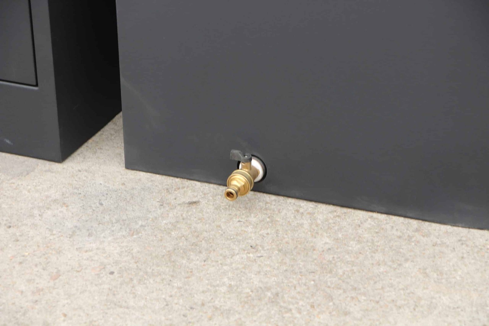
Confirm where the water is allowed to go
A drain destination is a site and jurisdiction decision. Depending on the project, water may contain treatment chemicals, cleaning products, dirt or biological load. The acceptable route can depend on the sanitary system, industrial or trade-waste rules, stormwater protection, septic limits, treatment method and local facility policy. Do not publish one universal disposal instruction.
The U.S. Centers for Disease Control and Prevention explains that the Model Aquatic Health Code is voluntary guidance that jurisdictions may choose to adopt for public aquatic venues. A cold plunge may or may not fall within an adopted aquatic-venue framework. The source is useful because it demonstrates that water operation and facility requirements can depend on local adoption and public-health authority; it is not proof that one MAHC provision applies to every OMNI installation.
Record the responsible reviewer and approval evidence for the destination. “Floor drain” is only a physical description. The buyer still needs to know what system it connects to, whether the event is permitted, whether a trap or backflow measure is required by the project, and how the route is kept available and maintained.
For an outdoor project, rainwater and landscape drainage add separate boundaries. The outdoor cold plunge site guide covers weather, runoff and seasonal operation. Do not route treated drain-down into a stormwater path merely because the equipment is outside.
Eight fields in a cold plunge chiller floor drainage schedule
| Field | Required record | Weak answer to reject |
|---|---|---|
| 1. Equipment and room identity | Tub, chiller, pump/filter, site, drawing revision and responsible parties | “Spa room” |
| 2. Five water events | Source, expected condition, volume/rate basis and event frequency | “Water may spill” |
| 3. Capture boundary | Wet zone, floor finish, tray/curb/threshold and protected dry areas | One drain symbol |
| 4. Conveyance route | Slope/fall basis, hose or pipe, valves, high points, crossings and setup method | “To nearby drain” |
| 5. Receiving destination | Connected system, capacity basis, discharge permission and reviewer | Unidentified floor opening |
| 6. Service and emergency response | Isolation, detection, containment materials, safe access and responsible person | “Call maintenance” |
| 7. Acceptance test | Test event, water quantity/rate, observation points, criterion and result | Photograph of a dry floor before use |
| 8. Handover and change rule | Cleaning/inspection routine, retained record and changes requiring review | No action after a hose, tub or room change |
Cold plunge chiller floor drainage is accepted when another reviewer can trace each event from source to destination and reproduce the test. The record should also show what remains unknown or conditional. A sophisticated floor finish does not compensate for an unapproved discharge route.
Test the installed route before routine use
Commission drainage in stages. Do not begin with an uncontrolled full drain-down.
- Inspect the room against the approved drawing: drain location, thresholds, routes, valves, trays, electrical separation and service access.
- Introduce a small controlled quantity at each capture point and confirm direction, ponding and hidden escape paths.
- Test the planned service-water task with the actual container or drain hose.
- Run the approved drain-down method at the stated valve position or pump setting while observing the receiving route.
- Operate the cold surfaces under representative conditions and inspect for condensation outside the planned wet zone.
- Record deviations, drying/cleaning, final condition and the person authorized to accept or hold the route.
The cold plunge chiller commissioning checklist connects this drainage result to equipment identity, electrical readiness, water-loop verification, controlled running and handover. Drainage passing alone does not release an installation with a leak, unknown electrical condition or failed flow requirement.
Retest after material changes: a different tub, relocated chiller, longer drain hose, new cabinet, raised floor, door threshold, filter arrangement, changed water treatment or new discharge restriction. Keep the original result so the reviewer can see what changed.
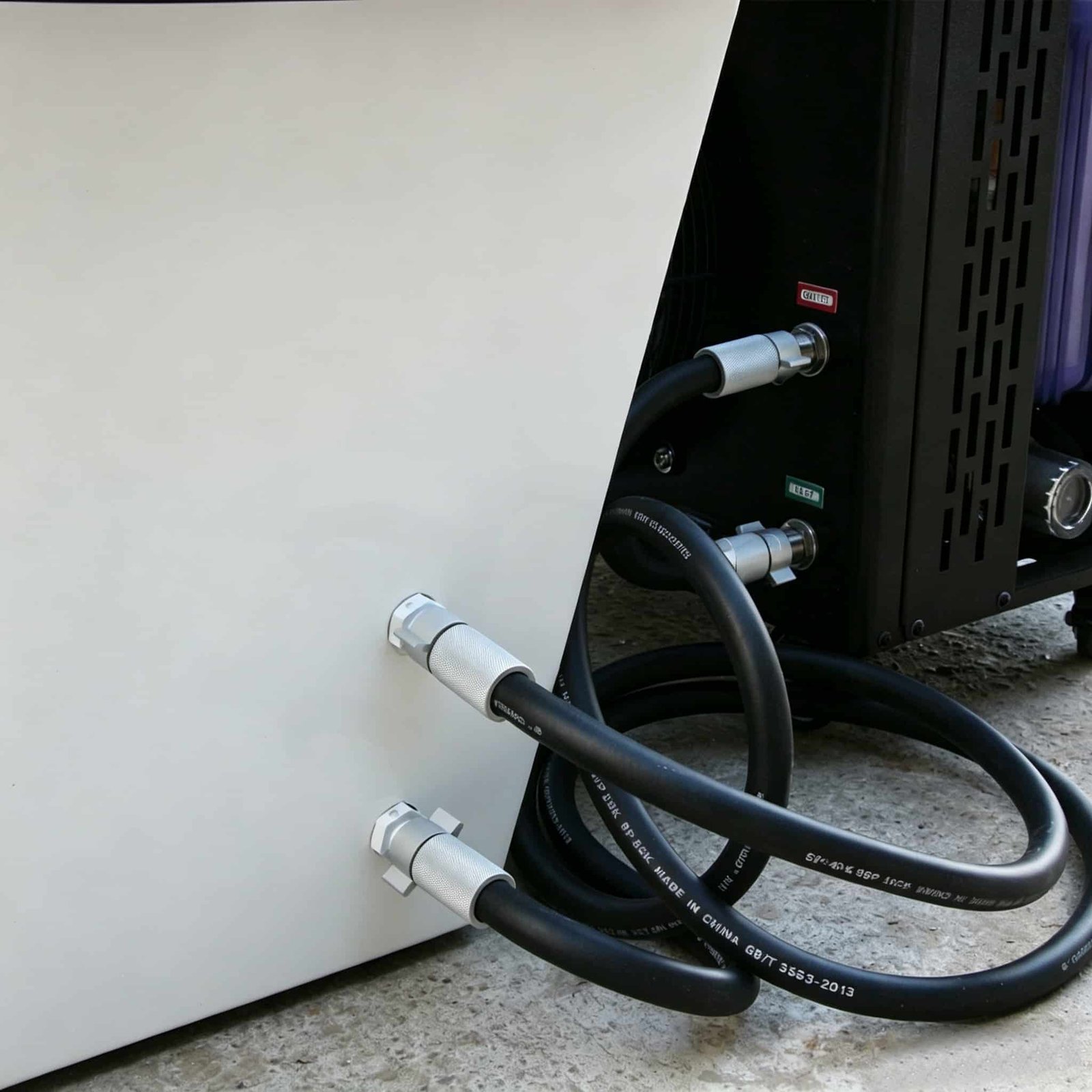
Illustrative failure: the drain exists but the room still floods
Illustrative scenario, not an OMNI customer case: a commercial room has a floor drain two metres from the tub. The design is approved from a plan view. After installation, the chiller sits on a low plinth between the tub and drain, the door threshold forms another barrier, and the portable drain hose must cross the user entrance.
Small condensation remains behind the plinth. Filter service water runs toward an electrical cabinet. During full drain-down, the hose moves and discharges onto the walking route. The floor drain itself is open and functional, but the cold plunge chiller floor drainage system fails because three event paths never reach it safely.
The revision maps the five events separately. Condensation receives an inspectable collection path; filter service gets a fixed container position; planned drain-down uses a restrained hose route during a controlled closure period; splash is contained inside the wet zone; abnormal leakage has a reachable isolation and response plan. The project then repeats the staged acceptance test.
This scenario shows why “floor drain provided” is not a measurable result. It does not prescribe a plinth, curb, tray or hose method for every room. The correct solution depends on the exact equipment, building and approved discharge route.
Copyable cold plunge chiller floor drainage record
- Project identity: site, room, drawing revision, tub, chiller, pump/filter and responsible reviewers.
- Water events: condensation/drips; splash/overflow; drain-down; service water; abnormal leak.
- Event basis: expected volume, rate, duration, frequency and water/treatment condition where known.
- Wet/dry boundaries: floor finish, containment, thresholds, walking route, electrical and building openings.
- Route: source, outlet, hose/pipe, valve, high points, fall/slope basis, collection point and setup method.
- Destination: receiving system, capacity confirmation, discharge permission, trap/backflow/project requirements and reviewer.
- Response: detection, isolation, spill-control material, safe shutdown access, cleaning/drying and escalation contact.
- Acceptance: staged test method, quantity/rate, observations, deviations, final result, approver and retest triggers.
Add the record to the OEM cold plunge chiller RFQ and room-interface package. To review an OMNI configuration, send the room plan, tub and chiller arrangement, five water events, intended drain-down method and locally approved destination. A useful drainage review should return a traceable route and test plan, not only the words “floor drain nearby.”
Questions buyers ask about floor drainage
Is one floor drain enough for a cold plunge room?
Only when the five water events can reach it safely, the receiving system can accept the planned event, and the route does not cross protected dry areas, electrical equipment, thresholds or uncontrolled walking paths.
Should tub drain-down go directly to a floor drain?
That depends on the tub outlet, hose or pipe, discharge rate, receiving capacity, water condition and local permission. Define and test the exact route rather than assuming direct discharge is acceptable.
Does condensation mean the tub or hose is leaking?
Not necessarily. Moisture can condense on surfaces below the surrounding dew point. Dry the area and observe where water first forms, while inspecting joints and levels so a real leak is not dismissed as condensation.
What should be tested during cold plunge chiller floor drainage commissioning?
Verify each capture point, floor direction and ponding, service-water collection, the controlled drain-down route, representative condensation, receiving capacity, protected dry areas, cleanup and the leak-isolation response.
When should the drainage plan be reviewed again?
Review it after changing the tub, chiller position, hoses, filter arrangement, cabinet, floor or threshold, drain-down method, water treatment, discharge destination or any condition that changes a water event or route.