Cold plunge chiller pump head must be selected at the required water flow through the complete installed loop, not from a pump’s maximum-flow or maximum-head label. The usable duty point is where the pump curve intersects the system curve created by the chiller, filter, hoses or pipes, valves, fittings and the actual loop arrangement. If those losses are not defined, a larger pump is only a larger unknown.
This article is for OEM buyers, equipment integrators and installers specifying a circulation pump before installation. It provides seven design inputs, a pressure-to-head calculation, a clean/dirty comparison and a copyable supplier schedule. It does not publish one universal pump size, flow or head for every cold plunge; the exact chiller and pump data, water temperature, configuration and approved installation instructions remain controlling.
Cold plunge chiller pump head belongs to a duty point
A pump curve shows how much head a pump can produce at different flow rates. A system curve shows how much head the connected loop requires at those same flow rates. Their intersection is the expected operating point for that configuration. Change the filter, hose diameter, route, valve position or chiller, and the system curve moves.
The Hydraulic Institute’s pump fundamentals material describes the pump/system operating point as the intersection of the pump and system curves. Its combined pump and system curve reference applies to pumping systems generally, not to one OMNI model. The principle is directly useful: the pump and loop must be compared on the same flow-and-head axes.
Do not confuse the duty point with either end of a marketing curve:
| Published number | What it usually describes | Why it cannot select the pump alone |
|---|---|---|
| Maximum flow | Flow near very low external head under stated test conditions | The installed chiller, filter, hoses and fittings add resistance |
| Maximum head | Head near zero or very low flow | The system needs both flow and head at the same time |
| Rated or selected duty point | A defined flow and head on the pump curve | Useful only when it matches the complete system curve and operating limits |
| Measured field flow | Actual flow at a stated measurement point and system condition | Confirms the installation but does not replace the design record |
The cold plunge chiller flow-rate record owns the field measurement and acceptance method. This page owns the design decision that must come first: which cold plunge chiller pump head is required to place the system inside the permitted flow range.
Seven inputs for cold plunge chiller pump head selection
Request all seven inputs before choosing a pump or accepting an integrated pump arrangement. If one value is unavailable, mark the selection provisional and state how it will be verified.
| Input | What to request | Common weak answer | Decision enabled |
|---|---|---|---|
| 1. Required flow window | Minimum, preferred and maximum permitted flow for the exact chiller/configuration and stated water condition | “Use a strong pump” | Defines the horizontal operating range |
| 2. Chiller pressure drop | Pressure loss versus flow through the exact water-side heat exchanger and internal path | One pressure-drop number with no flow | Adds the chiller loss to the system curve |
| 3. Filter/strainer states | Clean loss and the service/dirty condition used for design or alarm planning | Clean filter only | Shows whether flow remains acceptable before maintenance |
| 4. Hose or pipe route | Inside diameter, material, total supply/return length, temperature and route | Outside diameter or “two standard hoses” | Supports friction-loss calculation |
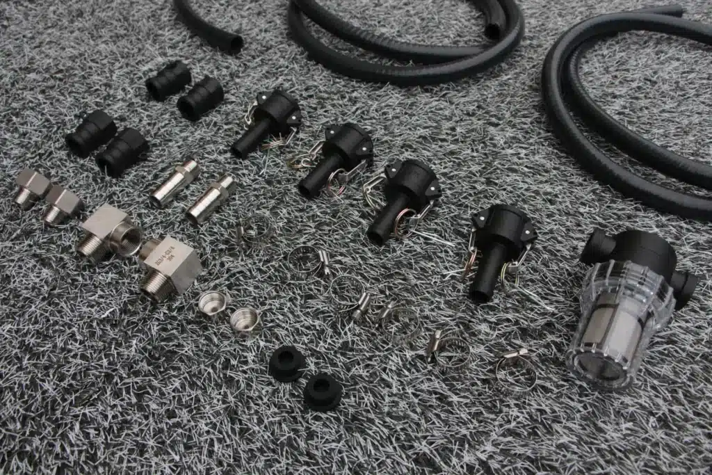
| 5. Fittings and valves | Quantity/type of elbows, tees, quick connectors, check valves, isolation valves and other restrictions | “Accessories included” | Captures minor losses that can become material in compact loops |
| 6. Loop topology and levels | Open or closed route, tank water levels, pump position, suction condition, high points and discharge point | Vertical distance from floor to tub rim only | Separates static head, priming and local pressure concerns |
| 7. Pump/control evidence | Full pump curve, speed/setting, permitted operating region, material/temperature limits and control method | Maximum litres per hour and wattage | Allows the curve intersection and adjustment method to be reviewed |
Cold plunge chiller pump head is a system value, not a product-family slogan. A pump that works with one short, clean integrated loop may miss the flow window after longer hoses, a finer filter, additional fittings or a different chiller are installed.
The filter and restriction guide explains how a developing blockage changes flow. For a shared facility with external components, use the complete filter-system boundary so the pump schedule includes every water-side item.
Build a transparent system-head calculation
Use one flow grid for the pump curve and every system loss. At each candidate flow, add the applicable static component and the losses through the chiller, filter, hoses/pipes, fittings, valves and accessories.
System head at flow Q:
Hsystem(Q) = Hstatic + Hchiller(Q) + Hfilter(Q) + Hpipe(Q) + Hfittings(Q) + Hother(Q)
When a supplier gives pressure drop instead of head, convert it using:
H = ΔP / (ρ × g)
where H is head in metres of the circulating liquid, ΔP is pressure difference in pascals, ρ is liquid density in kg/m³ and g is gravitational acceleration in m/s². For water near ordinary room temperature, 10 kPa is approximately 1.02 metres of water head. Use the actual liquid properties and engineering method when accuracy or additives matter.
Illustrative calculation, not an OMNI product specification: at one candidate flow, assume a documented chiller drop of 18 kPa, a clean filter drop of 7 kPa, hose/fitting loss of 9 kPa and no net static head between the same open reservoir levels. The total is 34 kPa, or about 3.47 m of water head. The selected pump must deliver the candidate flow at that head—not merely list a maximum head above 3.47 m.
Repeat the calculation for several flows to create the system curve. Do not add losses recorded at different flows as if they were interchangeable. Many friction-dominated losses rise roughly with the square of flow over a comparable turbulent operating region, but valves, filters, heat exchangers and transition zones should follow their actual supplier data where available.
The Hydraulic Institute’s system-curve reference explains how static and friction components combine and how parallel or series arrangements change a system curve. Use it as a general hydraulic method, then apply the exact cold-plunge component data.
Do not count elevation twice—or ignore priming
Elevation is often handled incorrectly in cold plunge chiller pump head estimates. In a full closed recirculating loop returning to the same reservoir level, the energy used to lift water on one side can be recovered as it returns, so the total vertical pipe run is not automatically added as permanent static head. Friction and component losses still remain.
An open arrangement can have real static head when the suction and discharge free-surface levels differ. A discharge above the source water level, a waterfall return, separate tanks or another open boundary can change the calculation. Draw the actual hydraulic levels rather than using the cabinet height or tub rim as a shortcut.
Even when net static head cancels, pump position and high points still matter. They affect filling, priming, trapped air, suction pressure and the risk of losing circulation. The selection package should show whether the pump is flooded, self-priming within its approved limits or dependent on a specific start-up method. Do not convert this article into a universal priming procedure; follow the exact pump and chiller instructions.
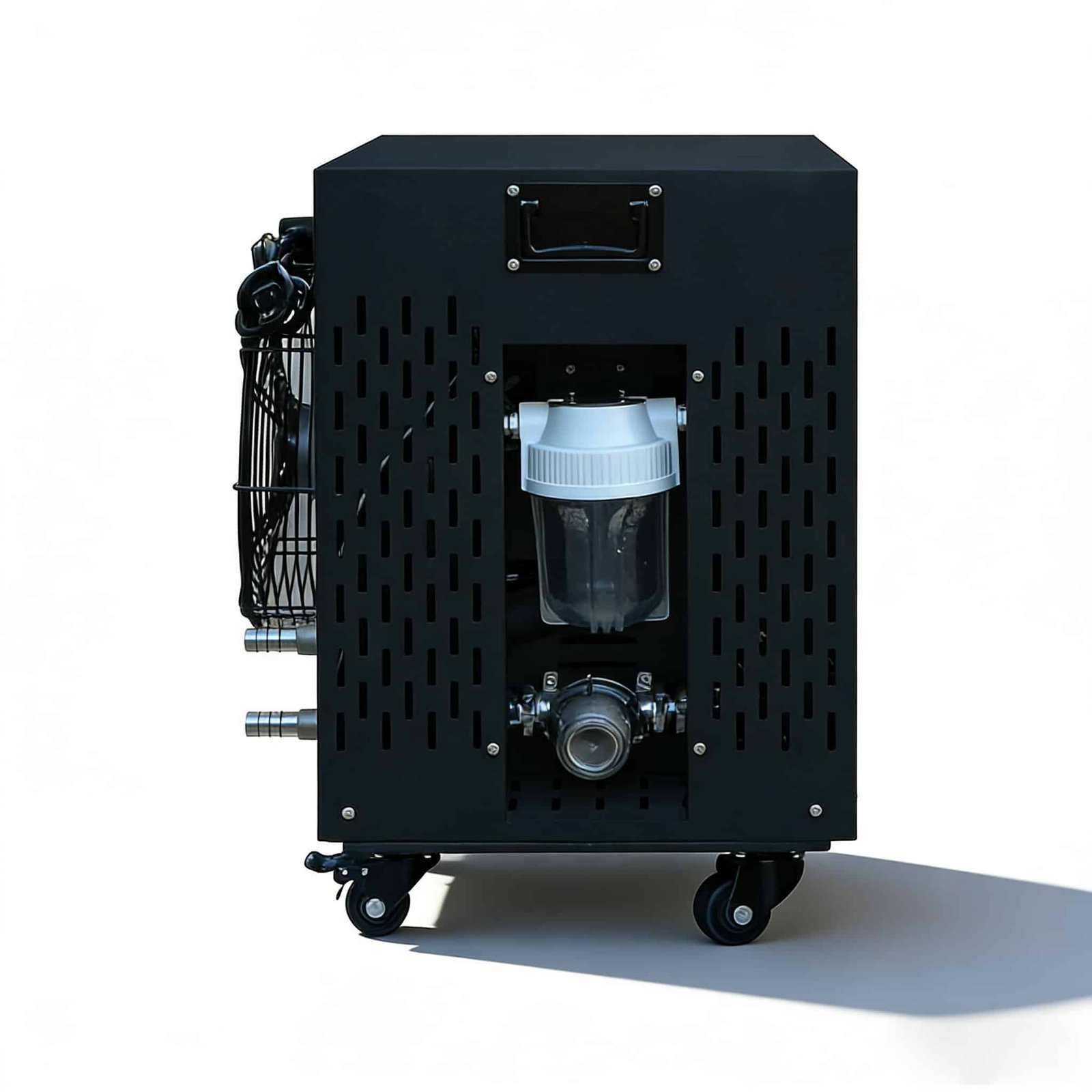
For integrated equipment, ask the supplier which water-loop boundary is already included in its cold plunge chiller pump head evidence. If the curve covers only the internal pump, external hoses, tub ports, filters or valves may still need to be added. If the supplier has validated a complete listed configuration, record every included component and the permitted route.
Use clean and service-condition pressure loss
A design that just reaches minimum flow with a new filter has no documented margin for normal fouling, a slightly longer hose route or manufacturing variation. Record at least two system states:
- clean/reference state: commissioned hoses, valves, filter and water level;
- service-trigger state: the agreed filter or pressure-loss condition at which maintenance, alarm or inspection is required.
Do not invent a universal dirty-filter multiplier. Ask for the filter manufacturer’s pressure-drop information or define a measured baseline and service rule during commissioning. The design question is whether the cold plunge chiller pump head can keep the loop inside the permitted flow window until the agreed maintenance trigger—not whether it can force water through an indefinitely blocked filter.
Quick connectors, check valves, narrow ports, sharp elbows and partially open valves can consume a meaningful share of a compact system’s head. List them individually or use an accepted equivalent-length/minor-loss method. A large hose cannot remove a restriction inside a smaller port or fitting.
The chiller water path also matters. A published water pressure drop must identify the exact model, internal configuration and flow. Do not substitute an air-side fan pressure curve for a water pump curve; they describe different media and systems. Do not borrow a pressure-drop value from another cabinet or voltage suffix without an approved model relationship.
Read the pump curve at the selected speed and fluid condition
The pump submission should show head versus flow over the relevant speed or setting, not one headline point. Mark the required flow window and overlay the clean and service-condition system curves. The intersections show whether the proposed pump can meet the chiller’s range in both states.
Record the pump model, curve revision, frequency/speed/setting, impeller or configuration where relevant, tested liquid, temperature and supply conditions. If the pump uses variable speed, identify the approved control logic or commissioning setting. “Variable” does not mean every speed is efficient, stable or acceptable for the chiller.
The U.S. Department of Energy’s Industrial Training and Optimization pump-systems resources emphasize system-level assessment and optimization rather than isolated component selection. The DOE material addresses industrial pumping broadly; it supports the same buyer discipline here: define the system requirement before choosing or adjusting the pump.
Ask the supplier to mark any prohibited or undesirable curve region, minimum continuous flow, overload limit, cavitation/NPSH requirement, material/temperature limit and allowed control method. Those details require the actual pump documentation and qualified design review. They should not be guessed from power rating or physical size.
Reject five common pump-selection shortcuts
| Shortcut | Why it fails | Required correction |
|---|---|---|
| Choose the largest L/h number | Maximum flow is measured near low head | Use flow at the calculated system head |
| Add the full vertical hose length as static head | A recirculating loop can recover elevation; topology matters | Draw free-surface levels and open/closed boundaries |
| Use only the clean filter | Normal loading shifts the system curve upward | Add the agreed service-condition loss and maintenance trigger |
| Oversize and throttle later | Can create noise, wasted energy, unstable control or excess pressure | Select a defensible duty point and approved control method |
| Use the pump label to approve the chiller flow | Delivered flow depends on the whole installed loop | Measure and record the actual field flow after installation |
A bypass or balancing valve can be part of a controlled hydraulic design, but it is not a universal repair for an incorrect pump. It changes the system curve and can hide a blocked main path if its position is not defined and recorded. The future bypass-valve decision should remain a separate system-control task rather than being used to make every pump selection appear acceptable.
Cold plunge chiller pump head should also respect component pressure limits. More available head can increase flow or pressure beyond what a heat exchanger, filter housing, hose, seal or tub fitting is designed to accept. Require maximum permitted pressure and flow for the complete offered configuration.
Verify the installed operating point
After installation, measure the flow at the approved point and record the system state: water level, pump setting, valve positions, hose route, filter condition, temperature and any active bypass. Compare the result with the chiller’s permitted flow range and the predicted curve intersection.
If measured flow differs materially from the prediction, do not immediately replace the pump. Check whether the installed loop matches the calculation: inside diameter, hidden quick connectors, valve position, reversed ports, trapped air, filter condition, added hose length and the exact pump setting. A mismatch can reveal an incomplete system schedule rather than a defective pump.
Use the commissioning acceptance gates to connect identity, site readiness, water loop, controlled running and signed handover. If the pump does not draw water or loses prime, switch to the cold plunge pump troubleshooting route; that page owns symptom diagnosis, not design selection.
Record a clean baseline and the maintenance trigger. The cold plunge chiller pump head calculation is complete only when the buyer can connect the predicted duty point to a reproducible field result and knows what condition requires cleaning, adjustment or escalation.

Copyable cold plunge chiller pump head RFQ schedule
- Chiller identity: exact model, water-side configuration, revision and permitted flow range.
- Duty target: minimum/preferred/maximum flow and the conditions behind that range.
- Chiller loss: pressure-drop-versus-flow data for the exact configuration.
- Filter/strainer: model, clean loss, service-condition loss and maintenance trigger.
- Route: hose/pipe inside diameter, material, supply/return lengths, high points and open/closed boundaries.
- Fittings: ports, elbows, tees, quick connectors, check/isolation/balancing valves and accessories.
- Pump evidence: model, full curve, setting/speed, fluid/temperature, approved region and limits.
- System curves: clean and service-condition calculations with the selected intersections marked.
- Field acceptance: measurement point/method, valve positions, filter state, accepted range and escalation rule.
Add this schedule to the OEM cold plunge chiller RFQ and the configuration review. To review an OMNI system route, send the exact chiller, tub, hose/pipe route, filter arrangement, target flow and destination electrical version. A defensible cold plunge chiller pump head decision should return a curve intersection and acceptance plan, not a bigger maximum-flow number.
Questions buyers ask about pump head
Is maximum pump head the cold plunge chiller pump head I should use?
No. Maximum head normally occurs near zero flow. Select the pump at the required flow and the total head of the complete installed loop, then verify the actual operating point.
Is pump head the same as pressure?
They are related but not identical expressions. Head represents energy per unit weight of liquid and can be calculated from pressure difference using the liquid density and gravity. State the units and conversion basis.
Does a taller tub always require more pump head?
No. The answer depends on whether the loop is open or closed and on the relevant free-surface levels. A full recirculating loop may recover elevation, while friction, component losses, priming and local pressures still matter.
How should a dirty filter affect pump selection?
Use a documented service-condition pressure loss or commissioning maintenance trigger. Confirm that flow stays within the permitted range until that trigger; do not assume an unlimited fouling allowance.
What proves the selected cold plunge chiller pump head is correct?
A complete system-loss schedule, pump and system curves with the duty point marked, component pressure/flow limits, and a commissioning record showing measured flow under the stated installed condition.