Cold plunge chiller redundancy should be selected from the maximum interruption the facility can accept, the critical cooling and circulation functions that must remain available, and the common failures that can stop both the duty and backup paths. Buying two chillers does not create N+1 resilience when they share one pump, filter, power circuit, room, control, drain route or unavailable service part.
This article is for gyms, hotels, wellness studios, distributors and commercial operators deciding whether to use N+1 capacity, duty/standby equipment, a stored quick-swap unit, critical spares or no hardware redundancy. It provides seven uptime decisions, a common-cause matrix, a recovery-time calculation and a copyable RFQ record. It does not prescribe one architecture for every site; user demand, water system, qualified service, space, budget and applicable local requirements remain project-specific.
What cold plunge chiller redundancy must decide
The decision is not “one chiller or two?” It is: which facility function must recover within what time after a defined failure, and which architecture can meet that target without sharing the same single point of failure?
Start by separating essential from desirable functions. A facility may need to keep one plunge available, preserve water circulation, protect water condition, prevent freezing or overheating, complete a supervised shutdown, or restore all guest capacity. Those are different continuity targets.
NIST defines a recovery time objective as the overall length of time components can remain in recovery before negatively affecting the organization’s mission or processes. That definition comes from information-system contingency planning, not cold-plunge equipment. The transferable buyer question is useful: how long can the paid or essential operation be unavailable before the impact becomes unacceptable?
The commercial cold plunge chiller planning guide owns the wider facility duty, users and utilities. Cold plunge chiller redundancy owns the failure-and-recovery architecture after the normal duty has been defined.
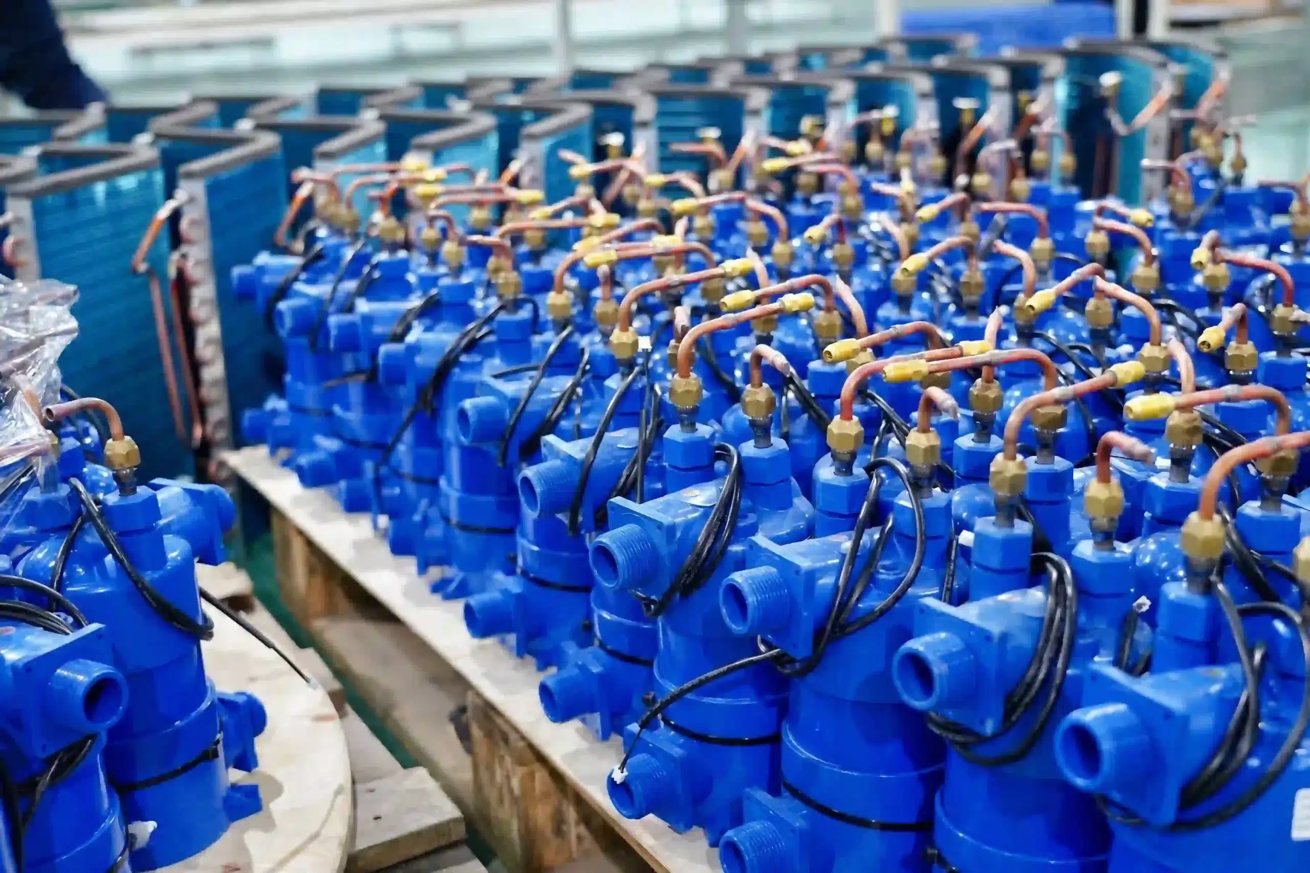
Seven decisions in a cold plunge chiller redundancy plan
| Decision | Required evidence | Weak answer to reject |
|---|---|---|
| 1. Essential service | Which tubs, circulation, water-care and safe-shutdown functions must remain available | “No downtime” |
| 2. Interruption target | Maximum acceptable outage, degraded capacity and recovery deadline by operating period | “As soon as possible” |
| 3. Failure scope | Equipment, pump/filter, power, control, room, drainage, water and service failures considered | Only compressor failure |
| 4. Architecture | N+1, duty/standby, portable spare, critical spares, external service agreement or accepted outage | “Buy two units” |
| 5. Isolation and switching | Valves, hoses/pipes, power, controls, water state, operator steps and qualified boundaries | “Connect the spare if needed” |
| 6. Recovery resources | Compatible model/revision, stored condition, tools, parts, people, access and recommissioning evidence | Spare exists somewhere |
| 7. Proof and upkeep | Standby tests, rotation, inspections, change control, records and failure drills | Backup tested when purchased |
A cold plunge chiller redundancy plan passes when another operator can state the protected service, failure boundary, recovery target, available path and evidence for returning the system to use. Extra equipment without a tested route is inventory, not continuity.
Define the acceptable interruption and degraded mode
Map the operating day. Record peak booking periods, minimum paid capacity, cleaning or maintenance windows, times when a controlled shutdown is acceptable and consequences of a longer outage. The recovery target can change by period; a hotel spa during booked hours may make a different decision from an unattended overnight holding condition.
Use a simple comparison:
Required recovery time ≥ detection + isolation + changeover/repair + prime/leak/flow checks + operating verification
If the required recovery time is shorter than the realistic process, change the architecture or reduce the promise. Do not delete priming, leak checks or recommissioning to make the schedule appear faster.
Illustrative calculation, not an OMNI service promise: a facility allows 60 minutes of interruption. Detection and safe isolation require 10 minutes, physical changeover 20, water-loop restoration 15 and verification 20. The total is 65 minutes, so a stored quick-swap unit does not meet the target under these assumptions. The site must shorten a verified step, use a faster standby route, change the target or accept controlled reduced service.
NIST’s functional recovery work focuses on restoring intended functions within acceptable time after disruption. It concerns buildings and lifelines, not cold-plunge products. The transferable principle is that “not destroyed” and “function restored on time” are different outcomes.
Compare four practical redundancy architectures
| Architecture | Useful when | Evidence needed | Main limitation |
|---|---|---|---|
| N+1 installed capacity | The critical load must continue after one defined unit is unavailable | Capacity at actual duty after one unit is removed; isolation and control sequence | Shared pumps, power, controls or water loop can defeat the extra chiller |
| Duty/standby installed unit | Fast switchover matters more than simultaneous capacity | Standby condition, valve/control state, rotation and proven changeover | Idle equipment can deteriorate or be incompatible after untracked changes |
| Stored quick-swap chiller | Hours rather than minutes of interruption are acceptable | Storage state, handling route, matching interfaces, tools and recommissioning time | Swap requires labour, drainage, movement and verification |
| Critical spares/service route | Failures are repairable within the allowed outage and competent service is available | Parts compatibility, diagnosis boundary, technician response and repair/retest method | A wrong diagnosis, unavailable technician or common failure can exceed the target |
No architecture is automatically superior. N+1 can protect capacity but increase controls, valves, maintenance and floor-space complexity. A stored spare can be cheaper but slower. Critical spares can reduce inventory cost but depend on diagnosis and qualified repair. The best choice is the simplest architecture that meets the documented interruption target and risk boundary.
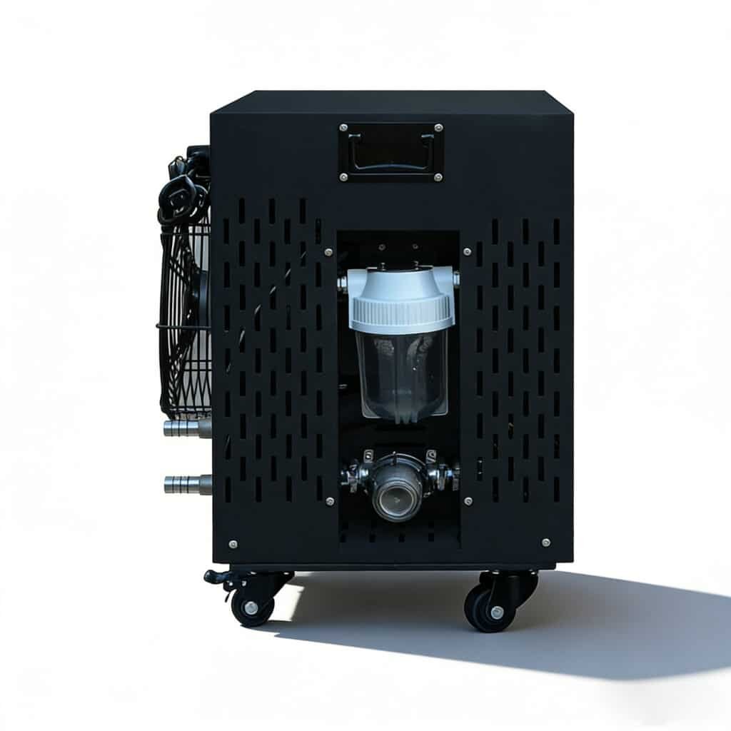
Cold plunge chiller redundancy should not use nameplate horsepower as the only interchangeability test. Confirm water-loop interfaces, permitted flow, pressure limits, electrical variant, controller behavior, cooling duty, ambient/site limits, service clearances and commissioning criteria for the exact configuration.
Prove that the remaining path can carry the critical load
Cold plunge chiller redundancy is only meaningful when the available system after the defined failure can support the minimum service. Use the decision test:
Available verified capacity after one defined outage ≥ critical operating load
Both sides need conditions. The remaining capacity should identify the exact chiller configuration, water volume, starting and operating temperatures, ambient range, flow condition, insulation/cover state and time basis. The critical load should identify the tubs or sessions that remain open, user sequence, acceptable temperature range and recovery window.
Illustrative capacity decision, not an OMNI performance claim: a site normally operates two equal plunge systems but defines one system as the critical degraded mode. If either chiller can independently support one approved tub under the relevant conditions and the water loop can isolate the failed side, two installed units may satisfy that particular N+1 objective. If both tubs must remain available after one failure, the same two units do not provide spare capacity.
Do not add nominal capacities from unrelated test conditions. One unit operating in a hotter room, with longer plumbing or a different filter/flow state may not reproduce another unit’s result. Cold plunge chiller redundancy also fails when the remaining equipment has theoretical capacity but cannot connect to the required tub or reject heat in the available location.
Record the post-failure operating limit, not only a pass label. The degraded mode may reduce simultaneous users, pause one tub, extend recovery time or require a cover between sessions. State who can activate that mode and which observation closes it. Cold plunge chiller redundancy should protect an explicit business function rather than an undefined promise of full normal operation.
Find the failures that stop both duty and backup paths
Draw the system boundary and mark every shared dependency. Two chillers can still form one fragile service when they depend on:
- one electrical circuit, disconnect, protective device or site supply;
- one circulation pump, filter, treatment train, manifold or blocked hose route;
- one controller, sensor, network account or permission;
- one room with inadequate heat rejection, drainage or environmental protection;
- one tub or shared water quality/contamination event;
- one unavailable technician, proprietary part, fitting or software process;
- one incorrect specification or change applied to both units.
Use a common-cause matrix:
| Shared dependency | Failure effect | Buyer decision |
|---|---|---|
| Power source | Both units unavailable | Accept outage, provide qualified alternate supply strategy or separate protected circuits where appropriate |
| Pump/filter loop | Cooling exists but circulation or treatment stops | Define redundant loop component, bypass/temporary route only if engineered, or fast repair |
| Room heat/drainage | Backup cannot operate safely in the same location | Fix the site boundary or place recovery equipment on an independent route |
| Controller/configuration error | Same failure repeated on both units | Preserve independent configuration evidence and change review |
| Service capability | Hardware available but no safe return-to-service decision | Define competent people, evidence, response time and escalation |
The floor-drainage plan, heat-rejection inputs and pump-duty method help identify shared site and water-loop dependencies. Redundancy cannot repair an unresolved room or hydraulic design.
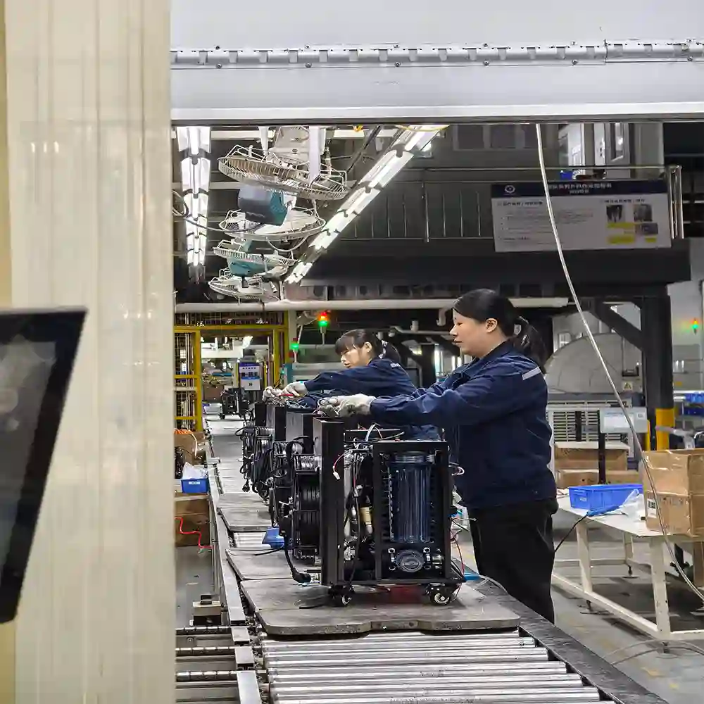
Plan isolation, switching and recommissioning
Document what changes when the duty path fails: which water and electrical connections are isolated, which valves or hoses move, how retained water is controlled, how the standby unit is primed, and which leak, flow, controller and operating checks release it.
A manual switchover can be valid when trained staff are present and the recovery target allows it. Automatic control can reduce response time but adds sensors, logic, valve actuators and failure modes. Do not call a system automatic failover unless the actual trigger, control authority, safe states, alarms and test evidence are defined.
The service-access schedule should prove that the duty unit can be isolated or removed without blocking the standby path. The commissioning gates define the identity, water-loop and controlled-run evidence required before the recovered system returns to service.
Cold plunge chiller redundancy should include a degraded-mode rule. If only one of two tubs remains available, state booking capacity, operating hours, water-care responsibilities and the conditions that require full closure. Staff should not improvise a reduced service while a major leak, electrical fault or water-quality event remains unresolved.
Match hardware redundancy to service and spare-parts reality
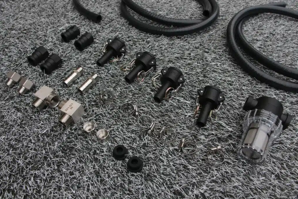
A backup strategy fails when the site cannot identify the spare, move it, connect it or obtain the qualified support required. Record exact model/revision, electrical variant, storage condition, maintenance state, accessories, hoses/fittings, manuals, passwords/permissions where applicable and the last verified readiness date.
For a repair-based strategy, list the failure modes the site can safely diagnose, the parts held locally, the replacement boundary, tools, technician response and post-repair test. Do not stock an impressive parts box without model/version mapping and condition checks. An unavailable seal, controller, pump or connector can make a larger spare component useless.
The nine-decision cold plunge chiller spare-parts kit expands this resource check into part criticality, model/revision mapping, replacement authority, storage and replenishment.
Use the maintenance baseline to keep duty and standby equipment in known condition, and the warranty evidence package to preserve identity, chronology and failure evidence. A warranty promise is not a recovery-time guarantee.
Prove the standby path before relying on it
Test cold plunge chiller redundancy under a controlled scenario. Identify the assumed failure, detect it, isolate the affected path, activate or install the recovery path, restore the water loop, verify flow/leaks/controls, observe the agreed operating condition and record elapsed time by stage.
Do not create unsafe faults or defeat protective devices to demonstrate redundancy. Use a test method approved for the exact equipment and site. Some exercises can begin from a planned shutdown rather than a simulated failure.
Repeat readiness checks at a justified interval and after changes to model, pump/filter, controls, power, hose route, room, software, storage or staff responsibility. Rotate duty/standby equipment only when the equipment documentation and operating plan support it. Record every open issue and the person who can hold or release the backup route.
FEMA’s continuity guidance is written for organizational continuity, not cold-plunge facilities. Its useful boundary is that continuity depends on essential functions, people, communications, facilities and resources together. Extra hardware alone does not create an executable recovery plan.
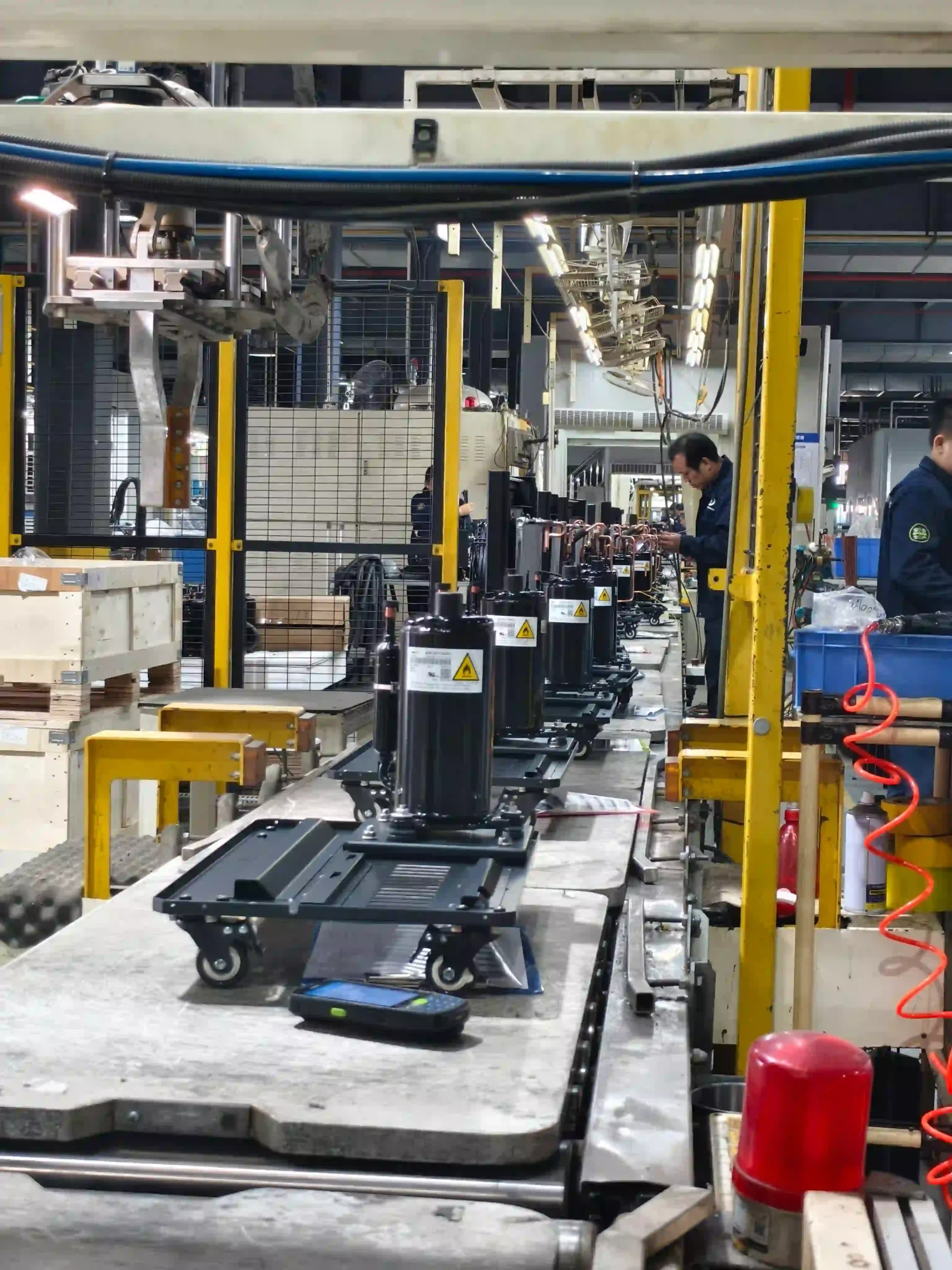
Illustrative choice: N+1 is not always the fastest recovery
Illustrative scenario, not an OMNI customer case: a studio operates two tubs and needs at least one available during booked hours. It considers three chillers as “N+1.” Review shows that all three use one pump/filter manifold and one electrical circuit. A pump, filter blockage or circuit fault stops the complete service.
The team compares alternatives. A second independent water-loop path would improve true N+1 capacity but needs more space, controls and maintenance. A stored quick-swap pump/filter module plus two independently isolatable chillers may meet the 90-minute recovery target with less complexity. A second electrical circuit and documented manual switchover are also required.
The chosen cold plunge chiller redundancy plan records protected capacity, failure assumptions, common dependencies, stored parts, switching sequence and a timed exercise. It does not claim zero downtime or that this architecture fits another facility.
Copyable cold plunge chiller redundancy RFQ record
- Facility duty: tubs, water volume, operating range, peak sessions, hours and minimum available capacity.
- Continuity target: acceptable outage, degraded mode, recovery deadline and high/low priority periods.
- Failure scope: chiller, pump/filter, power, controls, room, drainage, contamination and service resources.
- Architecture: N+1, duty/standby, stored spare, critical spares/service or accepted outage with reason.
- Independence: shared and separate power, water loop, controls, sensors, space, drainage and service dependencies.
- Compatibility: exact model/revision, electrical variant, interfaces, flow/pressure, capacity and controller evidence.
- Switching: detection, isolation, connections, priming, leak/flow/control checks and release authority.
- Resources: people, parts, tools, access, storage, documentation, service response and communication.
- Proof: timed exercise, result, deviations, maintenance/rotation interval and change triggers.
Add this record to the OEM cold plunge chiller RFQ. To review a facility architecture, send OMNI the critical load, allowed interruption, water-loop architecture, utilities, service capability and acceptance evidence required. A useful proposal should identify common failure points and recovery time, not simply quote a second machine.
Questions buyers ask about redundancy
Does buying two chillers create cold plunge chiller redundancy?
Not automatically. If both units share one power source, pump/filter loop, controls, room problem or unavailable service resource, one common failure can stop both. Record the protected function and every shared dependency.
What does N+1 mean for a cold plunge facility?
It should mean the required critical load remains available after one defined unit or path is unavailable. Prove that with configuration-specific capacity, isolation, utilities and control evidence rather than unit count alone.
Is a stored spare chiller enough?
Only when its model and interfaces are compatible, storage condition is controlled, trained people and tools are available, and the complete move, connection and recommissioning time meets the facility target.
How often should the backup path be tested?
Set an interval from equipment instructions, facility risk and change frequency, then retest after relevant equipment, control, water-loop, power, room, software or responsibility changes. Do not rely on the purchase-date test forever.
What is the first input for a redundancy quotation?
State the minimum service that must remain available and the maximum acceptable interruption under peak and non-peak conditions. Without that target, suppliers cannot compare N+1, standby, quick-swap or repair-based options fairly.