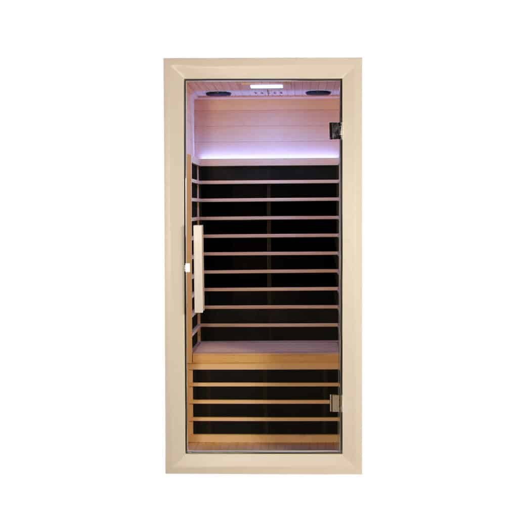
Commercial sauna ventilation must be designed around the exact room, heater, control sensors, occupancy and building ventilation method. A vent position copied from another cabin—or one air-change number copied from a blog—does not prove that a hotel, gym or spa sauna will operate as intended.
The buyer’s job is to make the ventilation boundary visible before the sample or room drawing is approved. The sauna supplier identifies model and heater constraints; the MEP designer connects them to the building system; the installer executes the approved details; and the operator keeps vents clear. This commercial sauna ventilation guide turns that shared responsibility into an RFQ, drawing and acceptance record.
Start commercial sauna ventilation with the exact room and heater
Commercial sauna ventilation is not a decorative grille decision. It affects how fresh air reaches occupants, how heated air moves, where exhaust leaves, how controls sense temperature and how the room interacts with the surrounding building. The correct arrangement can differ between an infrared cabin, an indoor stove room and an outdoor sauna.
Harvia’s official sauna heater manual says air in an electric-heater sauna should change six times per hour and shows different supply/exhaust positions for mechanical and gravity ventilation. It also warns that supply-air placement can affect the temperature sensor. Those are Harvia instructions for its design context, not universal approval values for every OMNI model or commercial building.
A serious commercial sauna ventilation brief therefore starts with the room model, inside dimensions, heater model and power, control/sensor package, intended occupancy, indoor or outdoor location, door arrangement and building ventilation method. If any of those fields is still unknown, the vent locations should remain open.
Define the ventilation design inputs before drawing vents
Use one coordinated commercial sauna ventilation input table instead of asking a factory to “add ventilation.” Each field changes what the supplier, MEP designer or installer must decide.
| Design input | What to record | Why it changes the plan |
|---|---|---|
| Room identity | Model, revision, internal volume, glazing and door arrangement | Air distribution and heat loss depend on the actual enclosure |
| Heat source | Infrared panels or exact stove/heater model, power and controls | Manufacturer vent and sensor instructions can differ |
| Occupancy | Approved user count, commercial schedule and turnover pattern | Public or repeated use changes fresh-air and operating review |
| Building system | Mechanical supply/exhaust, transfer air or approved gravity method | The sauna cannot be designed independently from the host building |
| Openings | Supply, exhaust, door undercut/transfer path and service access | A complete path is required; a grille alone is not a system |
| Control points | Temperature sensor, thermostat, limit sensor and controller locations | Air jets or stratification can distort sensing |
For commercial sauna ventilation, do not turn the word “ventilation” into a single supplier checkbox. Require a drawing that identifies every opening, its purpose, dimensions or scheduled airflow, relationship to the heater and sensors, and the party responsible for the building-side connection.
Buyers still choosing the heating experience can use the infrared versus traditional guide first. The ventilation brief should follow the selected room and heater, not precede them.
Keep infrared, indoor stove and outdoor rooms separate
OMNI’s Sauna Room Product Catalog 2026 shows why one commercial sauna ventilation layout cannot be copied across the range. Aura-D4 is listed on PDF page 18 as a 1350 × 1350 × 1950 far-infrared model with 3600 W power. Aura-S2 is listed on PDF page 22 as a 1350 × 1250 × 2000 stove-heated model with 3400 W power. Sol-D is listed on PDF page 39 as an 1800 × 1800 × 2000 outdoor stove model with 6500 W power.
The catalogue does not give a complete commercial sauna ventilation schedule for those rooms. That absence should become an RFQ field, not an invented public specification. A buyer should request the current room drawing, heater instructions, vent details and sensor arrangement for the quoted version.
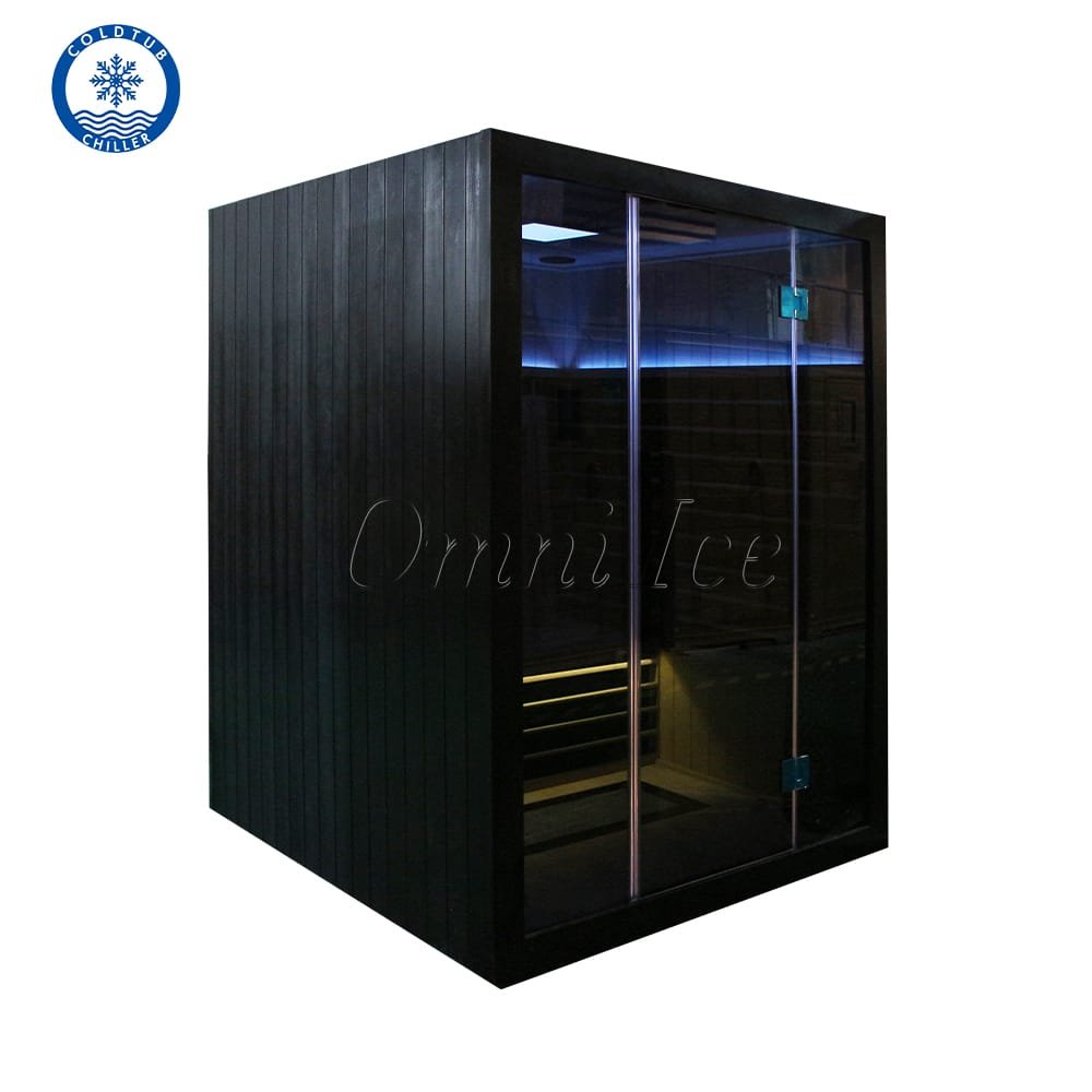
| Room example | Catalogue evidence | Ventilation question to close |
|---|---|---|
| Aura-D4 | Indoor far infrared; 1350 × 1350 × 1950; 3600 W | Panel layout, control sensors, transfer-air path and building connection |
| Aura-S2 | Indoor stove; 1350 × 1250 × 2000; 3400 W | Exact heater instructions, supply/exhaust positions and sensor coordination |
| Sol-D | Outdoor stove; 1800 × 1800 × 2000; 6500 W | Room air path, weather boundary, heater instructions and outdoor installation responsibility |
Use the indoor sauna range for enclosed building projects and the traditional sauna range when the stove-room route is already known. These category pages help select the family; the project drawing must still close the ventilation details.
Coordinate air inlets, exhausts, sensors and doors
Commercial sauna ventilation and controls cannot be reviewed separately. A supply jet near a sensor can make the control see a temperature that does not represent the occupied zone. An exhaust placed without a complete transfer-air path may not move air as intended. A door undercut may be part of the path in one approved design and irrelevant in another.
Commercial rooms need a complete air path through the occupied zone, not just a grille near the ceiling. The project team should check the selected heater instructions, the building system and the room geometry together. A general airflow sketch is not a substitute for the mechanical design or local approval.
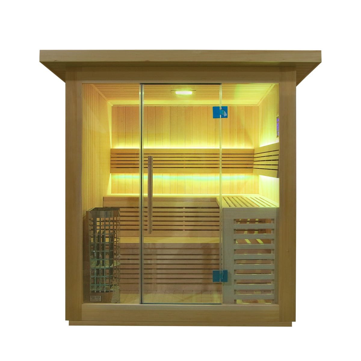
For a commercial sauna ventilation drawing, show the heater, benches, supply air, exhaust air, transfer path, door, sensor and service access on the same plan and section. Add arrows for intended flow only when the MEP designer has accepted them. A vent icon with no airflow basis or responsibility owner is not an approved design.
Assign responsibility and evidence
Commercial sauna ventilation fails most easily when each party assumes another party owns it. Put the responsibilities in the project file before production.
| Party | Provides | Must not assume |
|---|---|---|
| Sauna supplier | Room/heater identity, current instructions, sensor constraints and proposed vent drawing | That a catalogue room can connect to any building system unchanged |
| MEP designer | Airflow basis, building connections, controls coordination and applicable design review | That the factory grille positions are a complete mechanical design |
| Installer | Execution to approved drawings, sealed penetrations and field records | That site changes can be made without reapproval |
| Operator | Vent-clearance checks, cleaning, operating logs and issue escalation | That vents may be blocked by towels, storage or later fit-out |
The commercial sauna ventilation RFQ block should request: room model/revision; internal dimensions; heater and control version; intended occupancy; mechanical or gravity method; supply and exhaust locations; scheduled airflow or design basis; door/transfer-air detail; sensor positions; building-side scope; drawings; installation instructions; commissioning evidence; and the named approval owner.
Commercial buyers can route multi-user projects through the commercial sauna page. If the room type is not yet fixed, start at the broader sauna manufacturer page rather than forcing ventilation decisions onto an undefined model.
Use four ventilation gates instead of one approval box
A commercial sauna ventilation plan should pass four separate gates. The first is design intent: the project team agrees which air path, heater instructions and building connection are being used. The second is coordinated drawing review: vents, sensors, door transfer details, benches and heater appear on the same plans. The third is field verification: the installed openings and controls match the approved drawings before finishes conceal them. The fourth is commissioning and handover: the responsible party records the measured result, deviations and operating instructions.
| Gate | Evidence to retain | Hold if |
|---|---|---|
| Design intent | Room/heater identity, manufacturer instructions, ventilation method and approval owner | The heater or building ventilation method is still generic |
| Coordinated drawings | Plan and section showing supply, exhaust, transfer path, sensors, door and heater | Separate drawings conflict or omit responsibility |
| Field verification | Installation photos, opening sizes/locations, sensor positions and change record | Site penetrations or equipment differ from the approved set |
| Commissioning | Measured result, test conditions, corrective actions, final sign-off and operator handover | The project has no named party accepting airflow and controls |
This sequence keeps commercial sauna ventilation from disappearing between procurement and construction. A supplier can provide a room drawing while the MEP designer owns airflow values; an installer can execute both while the buyer controls the approval record. The file should show those boundaries rather than hiding them behind a single “ventilation included” line.
Example: a hypothetical hotel retrofit
Consider a hypothetical hotel preparing a commercial sauna ventilation plan for an Aura-S2-style stove room. The catalogue model helps establish a room format and heater class, but it does not prove that the existing room exhaust can serve the sauna. The hotel first records the room and heater version. Its MEP designer then checks the host building system, proposes supply and exhaust details and coordinates the heater sensor. The sauna supplier reviews the proposal against the selected room and heater instructions. The installer records the built openings before wall finishes close.
If the hotel later changes from an indoor stove room to a far-infrared cabin, the commercial sauna ventilation approval reopens. The old vent drawing cannot be carried forward just because the outside footprint is similar. Heater type, panels, controls, sensor locations and the manufacturer’s instructions have changed. The same rule applies when a private-label buyer changes the glass area, door arrangement or heater package after sample approval.
Record operating conditions without inventing universal limits
The handover file should state the intended commercial schedule, cleaning routine and checks for blocked vents. It should also name the conditions that trigger a service review: unusual temperature distribution, persistent odour, condensation outside the expected boundary, repeated control alarms or an unapproved room modification. These are escalation indicators, not a remote diagnosis.
Do not publish a universal commercial sauna ventilation rate from an unrelated manual. If the project uses a Harvia heater, Harvia’s instructions are relevant to that heater and arrangement. If another heater, room or ventilation method is selected, use its current instructions. The MEP designer should document the project airflow basis and the commissioning method used to verify it.
Freeze the ventilation drawing before production
A commercial sauna ventilation hold point should compare the supplier drawing, heater manual, MEP schedule and room layout. Release production only when the room identity, heater, vent openings, sensor locations, building interfaces and approval responsibilities agree.
Before commercial sauna ventilation handover, retain the approved drawings, installation photographs, measured airflow or commissioning record supplied by the responsible project party, sensor positions, door/transfer-air details and operator instructions. Record deviations and close them through the same approval owner. Do not invent a pass/fail airflow number from a different heater manual.
To request a coordinated review, send the destination country, venue, room family, intended occupancy, heater preference, available room dimensions, building ventilation information and required documents through the OMNI project contact. The output should be a list of confirmed fields and open responsibilities—not a universal promise that one vent layout fits every sauna.
Questions buyers ask
Can one ventilation rate be used for every commercial sauna?
No. Manufacturer guidance, heater type, room volume, occupancy, ventilation method, sensor location and local requirements can change the design. Use the exact heater and room instructions, then have the project team confirm the required airflow and vent locations.
Who should approve the sauna air inlet and exhaust locations?
The sauna supplier should provide model and heater constraints, while the project MEP designer and qualified installer coordinate those constraints with the building system and local requirements. The buyer should identify the final approval owner before production.
What ventilation evidence should be ready before sauna handover?
Keep the approved room and heater drawings, air inlet and exhaust locations, design airflow basis, sensor positions, door or transfer-air details, measured commissioning results, operating instructions and the names of the parties who accepted the installation.